ML432
1U Mic/Line Rack Mixer
953.024UK
Introduction
Thank you for choosing the Adastra ML432 mic/line mixer as part of your sound reinforcement system. This unit is designed to offer high quality, dependable service for audio mixing and distribution.
Please read this manual to gain the best results from your product and avoid damage through misuse.
Caution: Please read this manual carefully before operating Damage caused by misuse is not covered by the warranty
Safety Notice
- Prior to use, read through this manual.
- Keep the manual in good condition.
- Pay attention to safety warnings.
- Observe all operating requirements.
- Do not use the device near water or wet areas.
- For cleaning, only use a lint-free, dry cloth.
- Install according to the specifications.
- Place away from heat sources or heating appliances.
- Use mains lead provided and avoid damage to cable or connectors.
- Unplug power from mains during stormy weather or if unused for long periods.
- In case of malfunction, water ingress or other damage, consult qualified service personnel.
- Do not place in damp areas or near liquids or moisture. Do not spill liquids on the housing.
- Please pay attention to warning symbols during transit and placement.
- Terminals marked with the lightning symbol are HAZARDOUS LIVE and should only be connected by qualified personnel.
- Ensure that the apparatus is connected to a mains socket with a protective EARTH connection.
- Ensure correct operation of the mains switch.
Warning
- To prevent the risk of fire or electric shock, do not expose any components to rain or moisture.
- If liquids are spilled on the casing, stop using immediately, allow unit to dry out and have checked by qualified personnel before further use. Avoid impact, extreme pressure or heavy vibration to the case
- No user serviceable parts inside – Do not open the case
- Refer all servicing to qualified service personnel.
Safety
- Check for correct mains voltage and condition of IEC lead before connecting to power outlet
- Use only double-insulated wire for 100V connection to the mixer
Placement
- This unit can be used free-standing or fixed into a 19” rack
- Ensure adequate support and access to controls and connectors when rack-mounting
Cleaning
- Use a soft cloth with a neutral detergent to clean the housing as required
- Use a vacuum cleaner to clear ventilation grilles of any dust or debris build-ups
- Do not use strong solvents for cleaning the unit
Front Panel
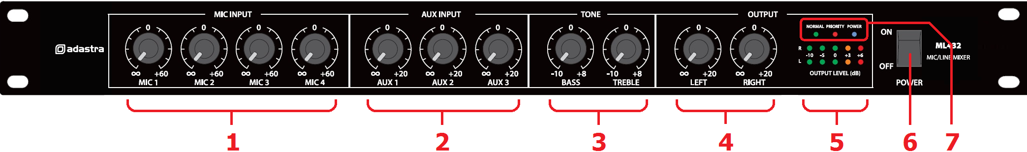 1. Mic inputs 1 - 4 level controls
2. Aux inputs 1 - 3 level controls
3. Global tone controls
4. Main Left + Right out level controls
5. L+R output meters
6. Power on/off switch
7. Normal / Priority / Power indicators
1. Mic inputs 1 - 4 level controls
2. Aux inputs 1 - 3 level controls
3. Global tone controls
4. Main Left + Right out level controls
5. L+R output meters
6. Power on/off switch
7. Normal / Priority / Power indicators
Rear Panel
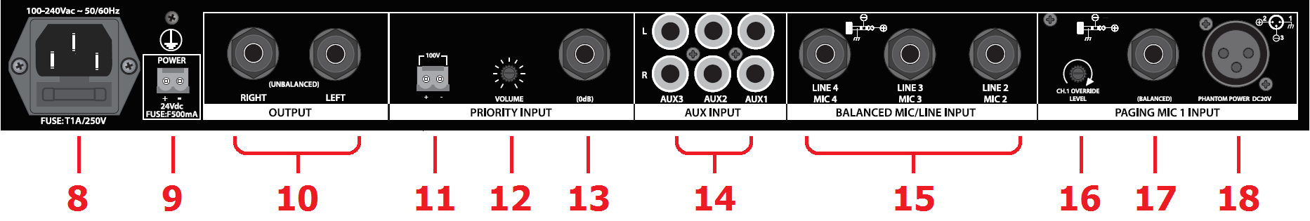
- Mains inlet IEC and fuse holder
- 24Vdc power contacts
- Main Left + Right 6.3mm jack outputs
- 100V line input terminals
- Priority input level control
- Line level input 6.3mm jack
- Aux line inputs - L+R RCA
- Mic.2 - 4 inputs - balanced 6.3mm TRS jack
- CH.1 Override Level adjustment
- Mic 1 input - balanced 6.3mm TRS jack
- Mic 1 input - balanced XLR
Connection
Ensure the Power (6) is switched off until all input and output connections are in place.
Turn all rotary level controls (1,2,4) fully down (anti-clockwise) to avoid loud noises when switching on.
Set the BASS and TREBLE Tone controls (3) to the vertical position (zero)
Connect the main microphone to the Priority input on the rear panel via balanced XLR (18) or 6.3mm jack (17)
If the microphone is a condenser type, use the balanced XLR input, which can provide +20V phantom power.
Further microphones can be connected to inputs 2, 3 and 4 via balanced or unbalanced 6.3mm jack (15)
(note: there is no phantom power for condenser mics. from inputs 2, 3 and 4)
Connect stereo line level sources to AUX 1 - 3 RCA inputs (14).
A separate priority input section has a 6.3mm jack for a mono line level input (13)
Also in this section are terminals for a 100V input for connection to an existing 100V PA system (11)
To do this, connect the “+” and “-” terminals in parallel with the speakers in an existing 100V system.
This input taps from the 100V line and converts it to a line input without affecting the 100V system itself.
Turn down the Priority Input level control (12) before powering up.
Connect the main Left and Right 6.3mm jack outputs (10) to the amplifier(s) or active speaker(s)
Connect the rear IEC inlet (7) to the mains using the supplied mains lead (or an equivalent approved type). Ensure that the supply voltage is correct for this equipment and that the mains outlet is switched on.
For mobile operation or away from mains supply, a 24Vdc input is provided on screw terminals.
Make sure the power switch is turned off before connecting to a 24Vdc power source and observe correct polarity before powering up the unit on DC power.
Operation
Ensure that amplifier(s) or active speaker(s) are switched off before powering up the ML432 mixer.
Switch on the power and the Power and Normal LED indicators should light (7)
Now switch on power to the amplifier or active speaker(s) and turn the volume(s) up part way.
Turn up the Left and Right output controls (4) half-way.
If connected, speak into a microphone whilst gradually turning up its channel level control (1)
If no microphones are connected, play a line level signal into a channel whilst gradually turning up its level.
The L+R output meters (5) should light up and the sound should be heard through the connected speakers.
Increase the Left & Right output levels if required and set the channel level control to the required volume.
Repeat the above steps for all connected inputs whilst balancing levels between channels as required.
For the AUX inputs, a single rotary control for each (2) adjusts the level of both left and right RCA inputs.
Sensible use of the output meters (5) will help to avoid overdriving the outputs and/or connected amplifiers.
The +6dB LED should only light briefly on percussive or transient parts of the sound (i.e. bass drum)
If the +6dB LED is lit for any longer than short bursts, the level controls will need to be turned down.
This will avoid signal clipping and overdrive, which can be damaging to equipment connected to the outputs.
For overall tone adjustment, moving the Tone controls (3) up or down can help improve the sound quality.
If the sound is too thin sounding, turn up the BASS rotary. If it is too deep sounding, reduce the BASS level.
If the sound is not very clear, turn up the TREBLE rotary. If it is too harsh sounding, reduce the TREBLE level.
A CH.1 override function can be set to suppress all other channel inputs when a signal is present on CH.1.
Speaking into the CH.1 mic will suppress the output of MIC 2-4 and AUX 1-3 and the Priority LED will light (7)
When CH.1 is silent, the other channels will resume normal volume level and the Normal LED will light (7)
The amount by which this function mutes the other channels is set by a rotary control (15) on the rear panel.
This same function is active for the priority line and 100V inputs (13, 11).
Turn up the priority input level control to enable these inputs and adjust to the required volume level.
Turn down amplifiers or active speakers before powering down the ML432 mixer to avoid loud noises.
Precautions
Indoor use only : The "House" symbol identifes electrical equipment designed primarily for indoor use.
Disposal : The "Crossed Wheelie Bin" symbol on the product means that the product is classed as Electrical or Electronic equipment and should not be disposed with other household or commercial waste at the end of its useful life. The goods must be disposed of according to your local council guidelines.
AVSL Group Ltd, Unit 2 Bridgewater Park, Taylor Road, Manchester, M41 7JQ, Unitied Kingdom
AVSL (EUROPE) Ltd, Unit 3D North Point House, North Point Business Park, New Mallow Road, Cork, Ireland