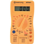
MTN-01
Digital Network Multimeter
600.105UK
Introduction
A handy digital multimeter with network tester that offers 19 testing ranges and 5 functions and comes supplied ready to use with shrouded testing probes and battery. The cable testing function uses a sequence of LED's on the main unit and remote unit to test lengths of RJ11, RJ12 or RJ45 cables for continuity and wire/pin-related faults.
Features
- Network cable test function with remote unit for RJ11, RJ12, and RJ45
- 3.5 Digit, 1999 count 0.5" LCD display
- 200-600V AC/DC Voltage, 10A DC current and resistance ranges
- Diode, transistor and continuity test functions
- Low battery indication
- Complies with EN61010 - 1:2010
- Supplied with shrouded testing probes and 9Vdc PP3 battery
Warning
To avoid possible electric shock or personal injury, and to avoid possible damage to the Meter or to the equipment under test, please adhere to the following rules:
Before using the Meter inspect the case. Do not use the Meter if it is damaged or the case (or part of the case) is removed. Look for cracks or missing plastic. Pay attention to the insulation around the connectors.
Inspect the test leads for damaged insulation or exposed metal. Check the test leads for continuity.
Do not apply more than the rated voltage, as marked on the meter, between the terminals or between any terminal and grounding.
The rotary switch should be placed in the right position and no changeover of range should be made during measurements being conducted to prevent damage of the Meter.
When the meter is working at an effective voltage over 60V in DC or 30Vrms in AC, special care should be taken due to danger of electric shock.
Use the proper terminals, function, and range for your measurements.
Do not use or store the meter in an environment of high temperature, humidity, explosive, inflammable, and strong magnetic fields. The performance of the meter may deteriorate after being exposed to moisture.
When using the test leads always keep your fingers behind the finger guards.
Disconnect circuit power and discharge all high-voltage capacitors before testing resistance, continuity, diodes or hFE.
Replace the battery as soon as the battery indicator appears. With a low battery, the meter may produce false readings that can lead to electric shock and personal injury.
Remove the connection between the testing leads and the circuit being tested and turn the meter power off before opening the meter case.
The internal circuit of the meter should not be altered at will to avoid damage of the meter and accidents.
A soft cloth and mild detergent should be used to clean the surface of the meter on a regular basis. No abrasives or solvents should be used to prevent the surface of the meter from corrosion, damage and accidents.
The meter is suitable for indoor use only.
Turn the meter power off when it is not in use and take out the battery when you are not using for a long period of time. Check the battery on a regular basis as it may leak when it has been out of use and replace as soon as any leaks appear to prevent damage to the meter.
The cable tester should not be used on any electrified product.
Do not use the cable tester on any network cable where the copper wire connectors are not fully pressed to avoid damage to the unit.
Any end not notified as 6P6C cannot be used to test telephone cables. As any disobeys may also cause damage to the unit.
Always use the correct quality tools to press the network cables.
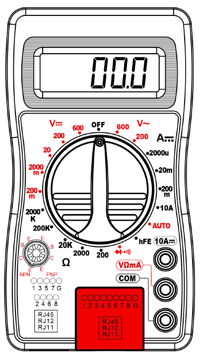
Overview
Technical Specifications
Accuracies are guaranteed for 1 year, 23℃±5℃, less than 80%RH
DC Voltage
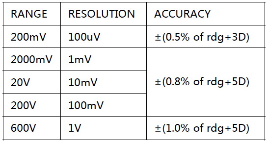
OVERLOAD PROTECTION: 220V rms AC for 200mV range and 500V DC or 500Vrms for all ranges.
AC Voltage
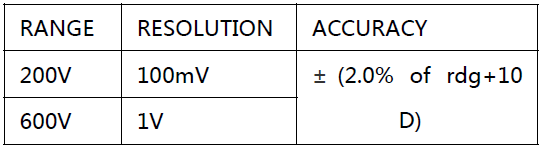
RESPONSE: Average responding, calibrated in rms of a sine wave.
FREQUENCY RANGE: 45Hz ~ 450Hz
OVERLOAD PROTECTION: 1000V DC or 750V rms for all ranges.
Audible Continuity
OVERLOAD PROTECTION:15 seconds maximum
220Vrms.
DC Current
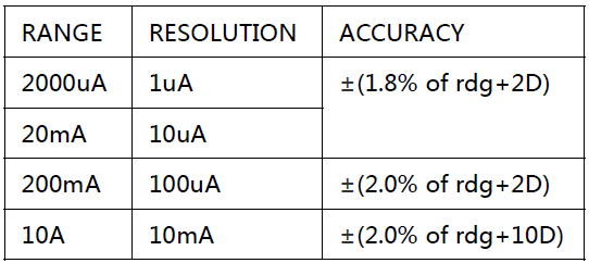
OVERLOAD PROTECTION: 500mA 250V fuse (10A range infused).
MEASURING VOLTAGE DROP: 200mV
Resistance
MAXIMUM OPEN CIRCUIT VOLTAGE: 3V.
OVERLOAD PROTECTION: 15 seconds maximum 220Vrms.
Operating Instructions
DC & AC Voltage Measurement
Connect red test lead to “VΩmA” jack, Black lead to “COM” jack.
Set RANGE switch to desired VOLTAGE position, if the voltage to be measured is not known beforehand, set the switch to the highest range and reduce it until a satisfactory reading is obtained.
Connect test leads to device or circuit being measured.
Turn on power of the device or circuit being measured and the voltage value will appear on the Digital Display along with the voltage polarity.
DC Current Measurement
Red lead to “VΩmA”. Black lead to “COM” (for measurements between 200mA and 10A connect red lead to “10A” jack with fully depressed.)
Set RANGE switch to desired DCA position.
Open the circuit to be measured, and connect test leads in SERIES with the load and with current to measure.
Read current value on Digital Display.
Additionally, “10A” function is designed for intermittent use only. Maximum contact time of the test leads with the circuit is 15 seconds, with a minimum intermission time of 15 mins between tests.
Resistance Measurement
Red lead to “VΩmA”. Black lead to “COM”.
Set RANGE switch to desired Ω position.
If the resistance being measured is connected to a circuit, turn off the power and discharge all capacitors before measurement.
Connect test leads to circuit being measured.
Read resistance value on Digital Display.
Section-1
Diode Measurement
Red lead to “VΩmA”, Black lead to “COM”.
Set RANGE switch to position.
Connect the red test lead to the anode of the diode to be measured and black test lead to cathode.
The forward voltage drop in mV will be displayed. If the diode is reversed, the figure “1” will be shown.
Section-2
Transistor hfe Measurement
Set RANGE switch to the hFE position.
Determine whether the transistor is PNP of NPN type and locate the Emitter, Base and Collector leads. Insert the leads into the proper holes of the hFE Socket.
The meter will display the approximate hFE value at the condition of base current 10μA and VCE2.8V.
Section-3
Audible Continuity Test
Red lead to “VΩmA”, Black lead to “COM”.
RANGE switch to position.
Connect test leads to two points of circuit to be tested. If the resistance is lower then 30Ω±20Ω, the buzzer will sound.
Cable Testing
(e.g., double twisted cables)
1. Insert cables to be tested into both main unit and remote tester sockets and turn the RANGE switch to AUTO.
2. The LED’s on both units should illuminate in sequence from 1 through to G for RJ45 cables and 1 through to 6 for RJ11 cables as below.
Main unit: 1-2-3-4-5-6-7-8-G (RJ45)
Remote unit: 1-2-3-4-5-6-7-8-G
Main unit: 1-2-3-4-5-6 (RJ11)
Remote unit: 1-2-3-4-5-6
Fault Description
1. If one cable is open circuit eg. no.3 then the no.3 LED on both units wont illuminate.
2. If a number of cables are open circuit then those number LED’s wont illuminate. If less than 2 cables are connected properly, none of the LED’s will illuminate.
3. If 2 cables are connected in the wrong order then the LED’s will illuminate in the same incorrect order. Eg. If no.2 and no.4 are twisted then the 2 displays will read as below:
Main unit: 1-2-3-4-5-6-7-8-G (RJ45)
Remote unit: 1-4-3-2-5-6-7-8-G
- If two cables are short circuited the corresponding LED’s on the remote unit wont illuminate. If 3 or more cables are short circuited then none of the LED’s on the remote unit will illuminate.
Battery and Fuse Replacement
Fuses rarely need replacement and blow almost always because of operator error.
If battery sign appears in display, it indicates that the battery should be replaced.
To replace battery & Fuse (F500mA/250V for mA terminal and F5A/250V for 5A terminal) remove the 2 screws in the bottom of the case, simply remove the old, and replace with a new one. Be careful to observe polarity.
Accessories
- Operator’s instruction manual
- Set of test leads (red and black)
- 9-volt battery, NEDA 1604 6F22 type
Specification
| Specification | Value |
|---|---|
| Power supply | 9Vdc (1 x PP3 supplied) |
| AC voltage | 200-600V |
| DC voltage | 200mV - 600V |
| DC current | 2000uA - 10A |
| Resistance | 200 Ohms - 2000K Ohms |
| Test lead length | 680mm |
| Dimensions | 126 x 70 x 26mm |
| Weight | 108g (including battery) |
Precautions
| CAUTION | ||
| RISK OF ELECTRIC SHOCK DO NOT OPEN | ||
| CAUTION : TO REDUCE THE RISK OF ELECTRIC SHOCK, DO NOT REMOVE COVER (OR BACK) NO USER-SERVICEABLE PARTS INSIDE REFER SERVICING TO QUALIFIED SERVICE PERSONNEL | ||
This symbol indicates that dangerous voltage constituting a risk of electric shock is present within this unit
This symbol indicates that there are important operating and maintenance instructions in the literature accompanying this unit
Safety Notice
- Prior to use, read through this safety guide.
- Pay attention to safety warnings.
- Observe all operating requirements.
- For any items designed for indoor use only, do not operate near water or in humid environments.
- For cleaning, only use a lint-free, dry cloth.
- Install according to the specifications.
- Place away from heat sources or heating appliances.
- During placement, ensure adequate support for the product and access to controls and connectors.
- Do not obstruct any cooling vents or openings and allow adequate space for air flow.
- Use only power connections supplied with the product or suitable equivalents.
- Do not modify the equipment in any way.
- For any mains powered appliances, ensure that the mains voltage is as described in the specifications.
- Keep powered products and batteries away from the reach of children.
- In case of malfunction, water ingress or other damage, consult qualified service personnel.
- Avoid pressure or impact to the housing that may result in damage when transporting or installing this product.
- For any Earthed mains product, ensure that the power supply has a protective Earth connection.
- Keep all packaging materials out of reach of children.
Disposal : The "Crossed Wheelie Bin" symbol on the product means that the product is classed as Electrical or Electronic equipment and should not be disposed with other household or commercial waste at the end of its useful life. The goods must be disposed of according to your local council guidelines.
AVSL Group Ltd, Unit 2 Bridgewater Park, Taylor Road, Manchester, M41 7JQ, Unitied Kingdom
AVSL (EUROPE) Ltd, Unit 3D North Point House, North Point Business Park, New Mallow Road, Cork, Ireland