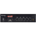
DM25
DM-Series Mixer-Amp with USB/FM and Bluetooth
953.108UK
Introduction
Thank you for choosing an Adastra DM-series mixer-amplifier as part of your public address system. This unit is designed to offer high quality, dependable service for mobile and installed systems.
Please read this manual to gain the best results from your product and avoid damage through misuse.

Caution: Please read this manual carefully before operating. Damage caused by misuse is not covered by the warranty.
Safety Notice
- Prior to use, read through this manual.
- Keep the manual in good condition.
- Pay attention to safety warnings.
- Observe all operating requirements.
- Do not use the device near water or wet areas.
- For cleaning, only use a lint-free, dry cloth.
- Install according to the specifications.
- Place away from heat sources or heating appliances.
- Use mains lead provided and avoid damage to cable or connectors.
- Unplug power from mains during stormy weather or if unused for long periods.
- In case of malfunction, water ingress or other damage, consult qualified service personnel.
- Do not place in damp areas or near liquids or moisture. Do not spill liquids on the housing.
- Please pay attention to warning symbols during transit and placement.
- Terminals marked with the lightning symbol are HAZARDOUS LIVE and should only be connected by qualified personnel.
- Ensure that the apparatus is connected to a mains socket with a protective EARTH connection.
- Ensure correct operation of the mains switch.
Warning
To prevent the risk of fire or electric shock, do not expose any components to rain or moisture.
If liquids are spilled on the casing, stop using immediately, allow unit to dry out and have checked by qualified personnel before further use. Avoid impact, extreme pressure or heavy vibration to the case
No user serviceable parts inside – Do not open the case – refer all servicing to qualified service personnel.
Safety
Check for correct mains voltage and condition of IEC lead before connecting to power outlet
Use double insulated speaker wire with adequate current rating for 100V speaker connections
Do not use 4-16Ω and 100V terminals at the same time
Do not connect 8Ω speakers to the 100V terminal or 100V speakers to the 8Ω terminal
Do not allow any foreign objects to enter the case or through the ventilation grilles
Placement
Keep out of direct sunlight and away from heat sources
Keep away from damp or dusty environments
For rack-mounting, use an appropriate shelf unit (e.g. 853.055UK) and ensure adequate support
Ensure adequate air-flow and do not cover cooling vents at the front and rear of the amplifier
Ensure adequate access to controls and connections
Cleaning
Use a soft cloth with a neutral detergent to clean the casing as required
Use a vacuum cleaner to clear ventilation grilles of any dust or debris build-ups
Do not use strong solvents for cleaning the unit
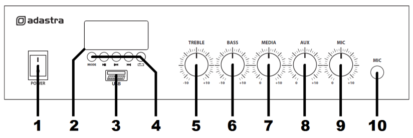
Front Panel
| No | Function |
|---|---|
| 1. | Power on/off switch |
| 2. | Media player display |
| 3. | USB media port |
| 4. | Media player mode & transport controls |
| 5. | Treble EQ |
| 6. | Bass EQ |
| 7. | Media player level |
| 8. | Auxiliary input level |
| 9. | Microphone level |
| 10. | Microphone input jack |
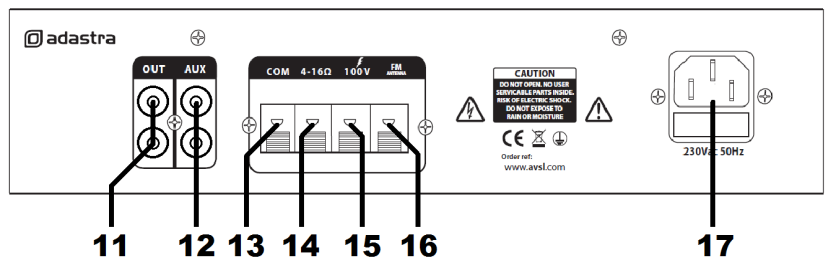
Rear Panel
| No | Function |
|---|---|
| 11. | Aux output connectors (RCA) |
| 12. | Aux input connectors (RCA) |
| 13. | COM speaker terminal |
| 14. | 4-16Ω speaker terminal |
| 15. | 100V speaker terminal |
| 16. | FM antenna connection |
| 17. | IEC mains inlet & fuse holder |
Connection and Setup
Connect the rear IEC inlet (17) to the mains using the supplied mains lead (or an equivalent approved type). Ensure that the mains voltage is correct and that the mains outlet is switched on.
Connect any line level audio inputs to the Aux input (12) on the rear panel using RCA leads.
Connect a microphone (if required) to the front panel jack input (10).
Further amplifiers can be connected from the rear Out RCA sockets (11).
The DM series amplifiers can be used either with 100V line or standard low impedance speakers.
These 2 configurations cannot be used together, so it is important to decide which method will be used at the start.
Speaker connections are provided as spring terminals on the rear panel (13, 14, 15)
Wiring is described for each type of speaker system on the following page.
Next to the speaker connections is a spring terminal for FM Antenna (16)
This should be connected to the core of an antenna cable for good FM radio reception (if required)
NOTE: Do not connect a speaker output to the antenna by mistake. This may carry high voltage.
100V Line Systems
For 100V line systems, connect the amplifier to the first speaker in the system using double-insulated speaker wire which has adequate current rating to handle the total output of the amplifier. Connect the “100V” (15) output terminal to the positive (+) connection of the speaker and “COM” output (13) to the negative (-) connection of the speaker. Connect further speakers in parallel to the first speaker with all positive terminals connected together and all negative terminals connected together as shown below.
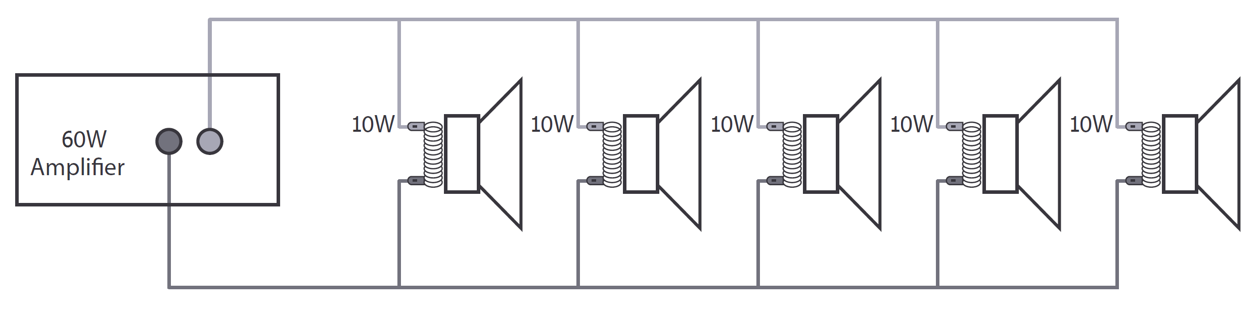
A 100V line speaker system can comprise of many speakers connected together. The determining factor for how many speakers can be used on a single amplifier is the power rating. For most purposes, it is advised to connect as many speakers as needed with a combined wattage of no more than 90% of the amplifier’s output power rating. The terminals of a 100V speaker are connected to a transformer and in some cases, this transformer may be “tapped” for different power ratings.
These tappings can be used to adjust the wattage (and output volume) of each speaker in the system to help achieve the ideal total power of the system for the amplifier.
Low Impedance Systems
The DM series amplifiers can alternatively provide an output for a single 4-16Ω speaker by connecting the “4-16Ω” output (14) to the positive (+) speaker connection and “COM” output (13) to the negative (-) speaker connection. It is important to ensure that the speaker load is no lower than 4Ω and that the power handling of the speaker is equal to or greater than the output power of the amplifier.
Operation
When all connections to the amplifier are made, turn all rotary controls down and switch on the power (1). Ensure a signal is being fed to the LINE IN connection and gradually increase the AUX rotary control (8) part way for checking.
Alternatively, connect a microphone to the Mic input (10) and gradually increase the Mic volume (9) for checking. The microphone should not be able to “hear” the speakers, which can cause feedback (squealing or howling noise).
The tone character of the output can be adjusted using the TREBLE and BASS controls. The zero setting for these is halfway (pointing vertically) and turning to the right boosts the BASS or TREBLE content, whereas turning to the left cuts the BASS or TREBLE content.
Note: If a mic or line input is not connected to the DM series amplifier, the initial test can be made using the built-in media player. See the information on the following pages for instructions.
Media Player
The DM series amplifiers are equipped with a built-in digital audio player which has 3 main modes.
Pressing the MODE button selects through Bluetooth, USB and FM tuner.
Output from this media player is governed by the Media level control (7) on the front panel and also
by pressing and holding the Previous or Next buttons.
Navigation for all 3 modes is provided by buttons beneath the LED display.
USB mp3 Audio Playback
 |
Input source selector - USB / FM / Bluetooth |
| Play / Pause track | |
| Previous track or hold for volume decrease | |
| Next track or hold for volume increase | |
| Repeat mode setting (ALL or ONE) |
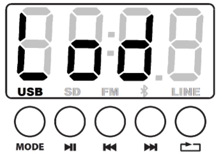
Push the USB pen drive into the USB port (3) and the display will show “Lod” to show that it is loading the media. Audio files will start to play automatically.
Warning: This USB port is designed for use with USB pen drives and is not suitable for powering other higher power devices or for charging smart phones or tablets.
Turn up the Media level control (7) gradually to hear the output from the speakers and increase to the required level.
If play does not start automatically, press the MODE button and/or Play/Pause button to check if the player is set to play from the required memory device.
Try Previous track and Next track buttons if the selected track is unable to play.
Otherwise, check that the audio files are standard mp3 type.
Normal playback will read through all tracks on the storage device. Press the Repeat button once to continually repeat ALL tracks in the device, press Repeat again to repeat just the ONE current track.
Pressing the Previous track button briefly steps backwards through tracks on the memory device. Press and hold this button to decrease the playback volume.
Pressing the Next track button briefly steps forwards through tracks on the memory device.
Press and hold this button to increase the playback volume.
To pause the current track, press the Play/Pause button and press it again to resume playback.
The LED digital display will show the track number when a track is selected and then the elapsed time when it is playing.
Bluetooth Mode
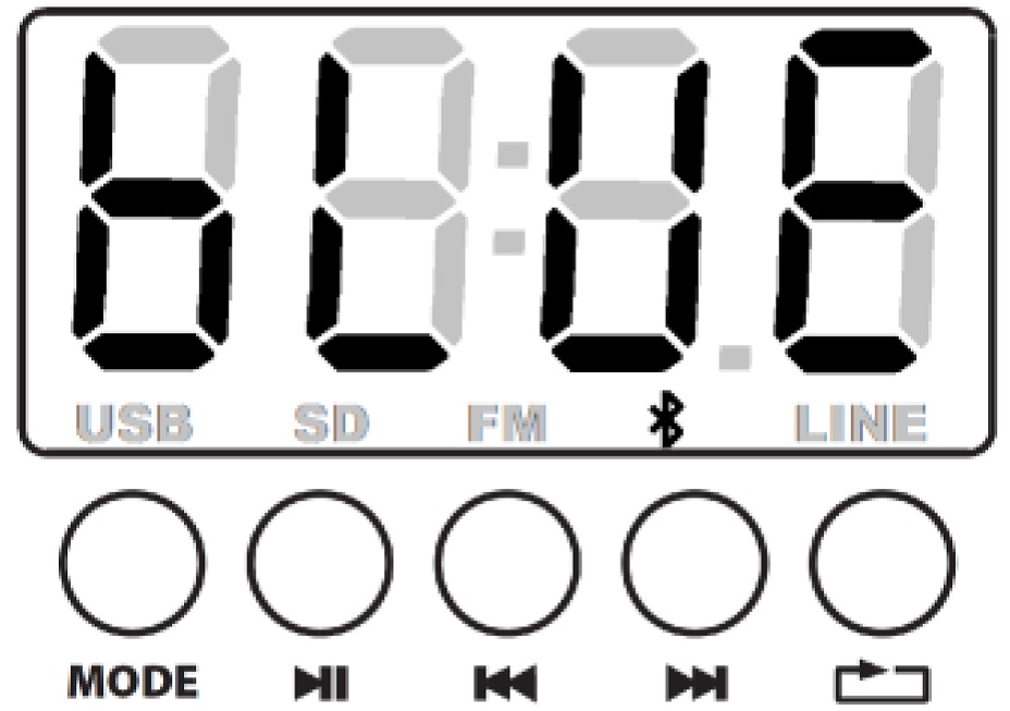
Pressing the mode button until the display shows “bLUE” enters Bluetooth receiver mode.
On a smart phone or other Bluetooth enabled device, scan for available devices and the DM series amplifier will be represented with the Bluetooth ID “MP3A”.
Select to pair with this device and once successful, wireless audio playback should be enabled through the media player of the DM series amplifier. If this does not happen, check that there are not more than 1 available devices with the ID “MP3A” and ensure that the volume is turned up on the sending device.
Once paired, the smartphone or other device should connect automatically when in range of the DM series amplifier and when Bluetooth is enabled.
FM Tuner
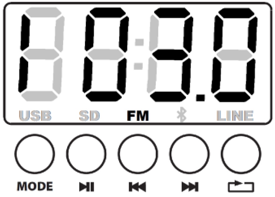
Pressing the mode button until “FM” appears in the lower part of the display enters FM tuner mode.
The display will show the current radio frequency in MHz.
Note: reception will be considerably better if an FM antenna is connected on the rear panel.
Press Play/Pause to initiate the auto-tune process, which will scan for the strongest frequencies and store them automatically as P01, P02, P03… etc.
These stored stations can then be navigated using the Previous and Next navigation buttons.
The Program number will be displayed, followed shortly by the tuning frequency.
Before powering down, turn down the level controls. To avoid loud pops through the speakers.
Troubleshooting
| Issue | Solution |
|---|---|
| No power LED on control panel | Ensure IEC lead is in good condition and connected properly |
| Check mains inlet fuse | |
| Ensure POWER switch is on | |
| LED display is lit but no output | Check input signals and condition of input connection leads |
| Check level controls are turned up | |
| Check file type on USB or connection via Bluetooth is OK | |
| Check MASTER, MIC, LINE IN or MEDIA controls are turned up | |
| Check speaker output terminals are connected correctly | |
| Check speakers are working (test on another amp if available) | |
| USB player will not play audio from media | Press PLAY on transport controls |
| Check memory device is connected properly (remove and re-insert) | |
| Check file types – standard mp3 files are required | |
| Check memory device works on a PC or Mac for standard playback | |
| No connection via Bluetooth | Check that the sending device is connected to the correct “MP3A” ID |
| Check the volume output level of the sending device | |
| Output is very loud or distorted | Check level of input signal is not too high |
| Turn down Level, Bass, Treble controls or reduce level of input signal | |
| Ensure Hi-Z line level input(s) not connected via MIC input | |
| Output is working but at very low level | Check input audio source level is not too low |
| Turn up Level, Bass and Treble controls | |
| Check for quiet recording of media files on USB | |
| Feedback from microphone | Face microphone away from speakers and monitors |
| Turn down MIC volume control | |
| Amplifier overheating | Ensure cooling vents are clear from debris and dust |
| Check that 4Ω or 8Ω speakers are not connected to 100V terminals | |
| Ensure total 100V speaker wattage is lower than the amplifier rating | |
| Ensure that 100V and 4Ω or 8Ω speakers are not both connected | |
| Ensure that total load connected to 4-16Ω output is not less than 4Ω |
Specification
| Specification | Value |
|---|---|
| Weight | 1.34kg |
| Power : output | 25Wrms |
| Power supply | 230Vac, 50Hz (IEC) |
| Audio source | USB player, FM tuner and Bluetooth receiver |
| Speaker : outputs | COM, 100V and 4-16 Ohms (spring terminals) |
| Controls | Treble, Bass, MP3, Aux, Mic |
| Fuse | T1AL |
| USB version | USB 2.0 (FAT32, 128GB max.) |
| Bluetooth version | 2.1 |
| Microphone : inputs | 6.3mm jack (unbalanced) |
| Line input | 2 x RCA (summed to mono) |
| Line output | 2 x RCA |
| Antenna connection | Spring terminal |
| Dimensions | 280 x 205 x 67mm |
Precautions
| CAUTION | ||
| RISK OF ELECTRIC SHOCK DO NOT OPEN | ||
| CAUTION : TO REDUCE THE RISK OF ELECTRIC SHOCK, DO NOT REMOVE COVER (OR BACK) NO USER-SERVICEABLE PARTS INSIDE REFER SERVICING TO QUALIFIED SERVICE PERSONNEL | ||
This symbol indicates that dangerous voltage constituting a risk of electric shock is present within this unit
This symbol indicates that there are important operating and maintenance instructions in the literature accompanying this unit
Safety Notice
- Prior to use, read through this safety guide.
- Pay attention to safety warnings.
- Observe all operating requirements.
- For any items designed for indoor use only, do not operate near water or in humid environments.
- For cleaning, only use a lint-free, dry cloth.
- Install according to the specifications.
- Place away from heat sources or heating appliances.
- During placement, ensure adequate support for the product and access to controls and connectors.
- Do not obstruct any cooling vents or openings and allow adequate space for air flow.
- Use only power connections supplied with the product or suitable equivalents.
- Do not modify the equipment in any way.
- For any mains powered appliances, ensure that the mains voltage is as described in the specifications.
- Keep powered products and batteries away from the reach of children.
- In case of malfunction, water ingress or other damage, consult qualified service personnel.
- Avoid pressure or impact to the housing that may result in damage when transporting or installing this product.
- For any Earthed mains product, ensure that the power supply has a protective Earth connection.
- Keep all packaging materials out of reach of children.
Disposal : The "Crossed Wheelie Bin" symbol on the product means that the product is classed as Electrical or Electronic equipment and should not be disposed with other household or commercial waste at the end of its useful life. The goods must be disposed of according to your local council guidelines.
AVSL Group Ltd, Unit 2 Bridgewater Park, Taylor Road, Manchester, M41 7JQ, Unitied Kingdom
AVSL (EUROPE) Ltd, Unit 3D North Point House, North Point Business Park, New Mallow Road, Cork, Ireland