MM321
Rack Mixer With Bluetooth & USB/FM Player
953.028UK
Introduction
Thank you for choosing an Adastra MM321 mic/line mixer with built-in media player as part of your sound reinforcement system.
This unit is designed to offer high quality, dependable service for audio mixing and distribution.
Please read this manual to gain the best results from your product and avoid damage through misuse.

Version 3.1
Caution: Please read this manual carefully before operating Damage caused by misuse is not covered by the warranty
Safety Notice
- Prior to use, read through this manual.
- Keep the manual in good condition.
- Pay attention to safety warnings.
- Observe all operating requirements.
- Do not use the device near water or wet areas.
- For cleaning, only use a lint-free, dry cloth.
- Install according to the specifications.
- Place away from heat sources or heating appliances.
- Use mains lead provided and avoid damage to cable or connectors.
- Unplug power from mains during stormy weather or if unused for long periods.
- In case of malfunction, water ingress or other damage, consult qualified service personnel.
- Do not place in damp areas or near liquids or moisture. Do not spill liquids on the housing.
- Please pay attention to warning symbols during transit and placement.
- Terminals marked with the lightning symbol are HAZARDOUS LIVE and should only be connected by qualified personnel.
- Ensure that the apparatus is connected to a mains socket with a protective EARTH connection.
- Ensure correct operation of the mains switch.
Warning
To prevent the risk of fire or electric shock, do not expose any components to rain or moisture.
If liquids are spilled on the casing, stop using immediately, allow unit to dry out and have checked by qualified personnel before further use. Avoid impact, extreme pressure or heavy vibration to the case
No user serviceable parts inside – Do not open the case – refer all servicing to qualified service personnel.
Safety
- Check for correct mains voltage and condition of IEC lead before connecting to power outlet
Placement
This unit can be used free-standing or fixed into a 19” rack
Ensure adequate support and access to controls and connectors when rack-mounting
Cleaning
Use a soft cloth with a neutral detergent to clean the housing as required
Do not use strong solvents for cleaning the unit
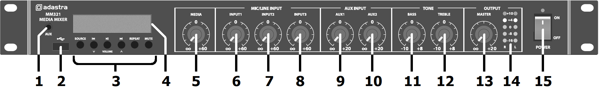
Front Panel
|
3.5mm AUX input to media player |
|
|
|---|---|---|---|
|
USB port |
|
|
|
Media player control panel |
|
|
|
Media player LCD display |
|
|
|
Media player level control |
|
|
|
Mic/Line input 1 level control |
|
|
|
Mic/Line input 2 level control |
|
|
|
Mic/Line input 3 level control |
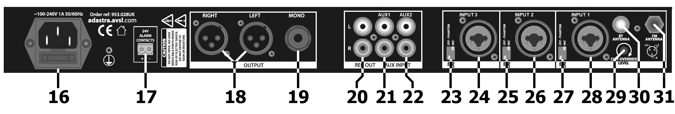
Rear Panel
|
IEC mains inlet and fuse holder |
|
Input 3 balanced XLR/jack |
|---|---|---|---|
|
24V emergency alarm contacts |
|
Mic/Line and phantom switches Input 2 |
|
L+R XLR balanced outputs |
|
Input 2 balanced XLR/jack |
|
6.3mm jack mono unbalanced output |
|
Mic/Line and phantom switches Input 1 |
|
Record output L+R RCA |
|
Input 1 balanced XLR/jack |
|
Aux 2 line input L+R RCA |
|
Ch.1 override level |
|
Aux 1 line input L+R RCA |
|
BT antenna connector |
|
Mic/Line and phantom switches Input 3 |
|
FM tuner antenna F connector |
Connection
Ensure the Power (15) is switched off until all input and output connections are in place.
Turn all rotary level controls (5 - 10) and Master level (13) fully down (anti-clockwise) to avoid loud noises when switching on.
Set the BASS and TREBLE Tone controls (11, 12) to the vertical position (zero)
Channels 1, 2 and 3 can accept microphones or mono line level inputs, such as CD, TV or electronic keyboard.
Connect the main microphone or line level signal to Mic/Line 1 input (28) on the rear panel via balanced XLR or 6.3mm jack.
If a condenser mic is being used, connect via XLR, select Mic level and 20V Phantom power on via the channel 1 DIP switches (27)
Further mic or line level signals can be connected to inputs 2 and 3 (24, 26) in the same way as for channel 1
Set the DIP switches for channels 2 and 3 (23, 25) to suit the input source.
Connect stereo line level sources to AUX 1 and AUX 2 RCA inputs (21, 22).
Outputs are available on L+R balanced XLR (18) for stereo operation and a single 6.3mm unbalanced jack (19) summed to mono.
Record outputs on L+R RCA (20) are unaffected by the Master level control.
For the FM tuner to function correctly, it is advisable to connect an FM aerial to the F type antenna connector (30)
If available, connect a 24V trigger from an alarm panel to the alarm contacts (17) to mute all except channel 1 in an emergency.
(The 24V contacts can be connected with either polarity +/- or -/+ to operate)
Connect the rear IEC inlet (16) to the mains using the supplied mains lead (or an equivalent approved type).
Ensure that the supply voltage is correct for this equipment and that the mains outlet is switched on.
Operation
Ensure that amplifier(s) or active speaker(s) are switched off before powering up the MM321 mixer.
Switch on the power and the Power LED indicator should light (15)
Switch on power to the amplifier or active speaker(s) and turn volume(s) up part way. Turn up the MM321 Master level (13) half-way.
If connected, speak into a microphone whilst gradually turning up its channel level control (6, 7 or 8)
If no microphones are connected, a line input or internal media player (see below) can be used for checking.
The L+R output meters (14) should light up and the sound should be heard through the connected speakers.
Increase the Master output level if required and set the relevant channel level control to the required volume.
Repeat the above steps for all connected inputs whilst balancing the levels between channels as required.
For the AUX line inputs, a single rotary control for each (9, 10) adjusts the level of both left and right RCA inputs.
Channel 1 input also has an override function which attenuates all other channels when there is a signal on Ch.1
Turning the CH.1 Override Level control clockwise increases the amount that it mutes all other channels.
Sensible use of the output meters (14) will help to avoid overdriving the outputs and/or connected amplifiers.
The +10dB LED should only light briefly on percussive or transient parts of the sound (i.e. bass drum)
If the +10dB LED is lit for any longer than short bursts, the level controls will need to be turned down.
This will avoid signal clipping and overdrive, which can be damaging to equipment connected to the outputs.
For overall tone adjustment, moving the BASS and TREBLE EQ controls (11, 12) can help to tailor the sound quality as required.
If the sound is too thin sounding, turn up the BASS rotary. If it is too deep sounding, reduce the BASS level.
If the sound is not very clear, turn up the TREBLE rotary. If it is too harsh sounding, reduce the TREBLE level.
Media Player
| SOURCE | REPEAT | |||
|---|---|---|---|---|
| bt = BT | Previous track | Play/Pause current track | Next track | ONE = repeat track |
| LOAD = loading USB | Hold = volume down | FM mode = Auto tune | Hold = volume up | rND = random play |
| MHz = FM frequency | In AUX mode = Mute | ALL = repeat all | ||
| AUX = Aux line input |
The MM321 built-in media player can play standard compressed audio files stored on a USB memory device (formatted to FAT32)
Insert the USB device into the USB port (2) to start playback using PREVIOUS, PLAY/PAUSE, NEXT & REPEAT controls.
The media player can also playback audio from a smart phone or tablet via B/T wireless connection.
Ensure the supplied B/T antenna is connected on the rear panel (31)
To pair a device to the MM3260, press the SOURCE button until “bt” appears in the LCD display.
On the smart phone or tablet, search for the device called “adastra” and select to pair and connect.
Once connected, playback from the device can be navigated by the PREVIOUS, PLAY/PAUSE and NEXT buttons.
For FM tuner mode, press SOURCE until a frequency (in MHz) is displayed. Press and hold PLAY/PAUSE to auto tune available stations
(pressing PLAY/PAUSE during this process will abort the auto-tuning) Use the PREVIOUS and NEXT buttons to navigate through the stored stations.
To delete any selected station, press and hold the Repeat button. Repeat the auto tuning process to re-populate any missing presets.
Connecting an external device to the 3.5mm AUX jack socket (1) allows playback of stereo line level audio through the media player.
All media player output is controlled by the MEDIA level control (5) on the front panel.
Turn down amplifiers or active speakers before powering down the MM321 mixer to avoid loud noises.
Specification
| Specification | Value |
|---|---|
| Power supply | 100-240Vac, 50/60Hz (IEC) |
| Fuse | T1AL |
| Inputs : Mic/Line | 3 x XLR (bal/unbal) |
| Inputs : Aux | 2 x L+R RCA |
| Input : line | 3.5mm jack to media player |
| Audio source | Internal Bluetooth, USB & FM player |
| Bluetooth version | 5.0 |
| Outputs | L+R XLR, Mono 6.3mm jack, Record out (RCA) |
| Emergency control | 24V contacts mute all except channel 1 |
| Phantom power | +20V (switchable channels 1-3) |
| Controls | Media, 3 x Mic/Line, 2 x Aux, Treble, Bass, Master level |
| Rear panel controls | Priority muting level, mic/line and phantom DIP switches |
| Input impedance | 2.2k Ohms (mic/line), 10k Ohms (aux) |
| Frequency response : mic | 20Hz - 18kHz |
| Frequency response : line | 14Hz - 20kHz |
| Frequency response : aux | 10Hz - 23kHz |
| Input sensitivity : mic/line | -45dBV |
| Input sensitivity : aux/line | -10dBV |
| Signal to noise ratio : mic | 55dB |
| Signal to noise ratio : aux/line | 60dB |
| THD | 0.05% |
| Dimensions | 482 x 130 x 44mm |
| Weight | 1.43kg |
Precautions
| CAUTION | ||
| RISK OF ELECTRIC SHOCK DO NOT OPEN | ||
| CAUTION : TO REDUCE THE RISK OF ELECTRIC SHOCK, DO NOT REMOVE COVER (OR BACK) NO USER-SERVICEABLE PARTS INSIDE REFER SERVICING TO QUALIFIED SERVICE PERSONNEL | ||
This symbol indicates that dangerous voltage constituting a risk of electric shock is present within this unit
This symbol indicates that there are important operating and maintenance instructions in the literature accompanying this unit
Safety Notice
- Prior to use, read through this safety guide.
- Pay attention to safety warnings.
- Observe all operating requirements.
- For any items designed for indoor use only, do not operate near water or in humid environments.
- For cleaning, only use a lint-free, dry cloth.
- Install according to the specifications.
- Place away from heat sources or heating appliances.
- During placement, ensure adequate support for the product and access to controls and connectors.
- Do not obstruct any cooling vents or openings and allow adequate space for air flow.
- Use only power connections supplied with the product or suitable equivalents.
- Do not modify the equipment in any way.
- For any mains powered appliances, ensure that the mains voltage is as described in the specifications.
- Keep powered products and batteries away from the reach of children.
- In case of malfunction, water ingress or other damage, consult qualified service personnel.
- Avoid pressure or impact to the housing that may result in damage when transporting or installing this product.
- For any Earthed mains product, ensure that the power supply has a protective Earth connection.
- Keep all packaging materials out of reach of children.
Disposal : The "Crossed Wheelie Bin" symbol on the product means that the product is classed as Electrical or Electronic equipment and should not be disposed with other household or commercial waste at the end of its useful life. The goods must be disposed of according to your local council guidelines.
AVSL Group Ltd, Unit 2 Bridgewater Park, Taylor Road, Manchester, M41 7JQ, Unitied Kingdom
AVSL (EUROPE) Ltd, Unit 3D North Point House, North Point Business Park, New Mallow Road, Cork, Ireland