MTM01
Professional Digital Multimeter
600.100UK
Introduction
This professional digital multimeter offers 32 testing ranges and 8 functions and comes supplied ready to use with a shockproof rubber holster, shrouded testing leads and battery.
Please read this manual thoroughly and ensure all contents are fully understood before using the apparatus.
Features
- Continuity test function
- Transistor test function
- Reading hold function
- Reading hold function
- Supplied with shrouded test leads, shockproof rubber holster and 9V PP3 battery
- Complies with EN61010 - 1:2010
Warning
To avoid possible electric shock or personal injury, and to avoid possible damage to the tester or to the equipment under test, adhere to these following rules:
Before using the tester inspect the case. Do not use the tester if it is damaged or the case (or part of the case) is removed. Look for cracks or missing plastic. Pay attention to the insulation around the connectors.
Inspect the test leads for damaged insulation or exposed metal.
Check the test leads for continuity.Do not apply more than the rated voltage, as marked on the tester, between the terminals or between any terminal and grounding.
The rotary switch should be in the right position and no changeover of range shall be made while measurement is conducted to prevent damage.
When the tester is working at an effective voltage over 60V in DC or 30Vrms in AC, special care should be taken for there is danger of electric shock.
Use the proper terminals, function, and range for your measurements.
Do not use or store the tester in an environment of high temperature, humidity, explosive, flammable, damp or of a strong magnetic field. The performance of the tester may deteriorate after being exposed to any of these elements.
When using the test leads, keep your fingers behind the finger guards.
Disconnect circuit power and discharge all high-voltage capacitors before testing resistance, continuity, diodes.F
Replace the battery as soon as the battery indicator appears. With a low battery, the meter may produce false readings that can lead to electric shock and personal injury.
Remove the connection between the testing leads and the circuit being tested and turn the meter power off before opening the meter case.
The internal circuit of the meter shall not be altered at will to avoid damage of the meter and any accident.
A soft cloth and mild detergent should be used to clean the surface of the tester on a regular basis. No abrasive and solvent should be used to prevent the surface of the tester from corrosion or damage.
The tester is suitable for indoor use only.
Turn the tester power off when it is not in use and take out the battery when not using for a long time. Check the battery regularly; replace the battery immediately if any signs of leaking appear. Battery acid will damage the tester.

Multimeter comparison table
| Model | DCV | ACV | DCA | ACA | Ω |  |
 |
hFE | Cap |
|---|---|---|---|---|---|---|---|---|---|
| MTP01 | Y | Y | Y | Y | Y | Y | Y | Y | Y |
Technical Specifications
Accuracies are guaranteed for 1 year, 23ºC ± 5ºC, less than 80% RH.
DC Voltage
| Range | Resolution | Accuracy |
|---|---|---|
| 200mV | 100uV | ±(0.5% of rdg + 3D) |
| 2V | 1mV | |
| 20V | 10mV | ±(0.8% of rdg + 5D) |
| 200V | 100mV | |
| 600V | 1V | ±(1.0% of rdg + 5D) |
Input Impedance: 10MΩ
Overload Protection: 1000V DC or 750V AC rms
Max. Input voltage: 1000V DC
AC Voltage
| Range | Resolution | Accuracy |
|---|---|---|
| 200V | 100mV | ±(2.0% of rdg + 10D) |
| 500V | 1V | ±(2.0% of rdg + 10D) |
Input Impedance: 10MΩ
Frequency Range: 40Hz ~ 400Hz
Overload Protection: 1000V DC or 750V AC rms
Response: Average, calibrated in rms of sine wave
Max. Input voltage: 750V AC rms
Audible Continuity
| DESCRIPTION | Remark | |
|---|---|---|
| Built-in buzzer sounds if resistance |
is less than 30±20Ω Open circuit voltage: about 2.8V |
|
| The approximate forward voltage drop will be displayed |
Open circuit voltage: about 2.8V |
|
Overload Protection: 250V DC/AC rms
DC Current
| Range | Resolution | Accuracy |
|---|---|---|
| 2mA | 1uA | ±(1.8% of rdg + 2D) |
| 20mA | 10uA | |
| 200mA | 100uA | ±(2.0% of rdg + 2D) |
| 10A | 10mA | ±(2.0% of rdg + 10D) |
Overload Protection:
mA: F0.5A/600V fuse
10A: F10A/600V fuse
Voltage Drop: 200mV
AC Current
| Range | Resolution | Accuracy |
|---|---|---|
| 2mA | 1uA | ±(2.0% of rdg + 2D) |
| 20mA | 10uA | |
| 200mA | 100uA | ±(2.0% of rdg + 2D) |
| 10A | 10mA | ±(2.5 of rdg + 10D) |
Overload Protection:
mA: F0.5A/600V fuse (DT9205A, DT9207A, DT9208A)
10A: F10A/600V fuse
Voltage Drop: 200mV
Frequency Range: 40Hz ~ 400Hz
Response: Average, calibrated in rms of sine wave
Resistance
| Range | Resolution | Accuracy |
|---|---|---|
| 200Ω | 0.1Ω | ±(1.0% of rdg + 10D) |
| 2KΩ | 1Ω | ±(1.0% of rdg + 4D) |
| 20kΩ | 10Ω | |
| 200kΩ | 100Ω | |
| 2MΩ | 1kΩ | |
| 20MΩ | 10kΩ | ±(1.0% of rdg + 10D) |
| 200MΩ | 100kΩ | ±[5%*(rdg-10) + 10D) |
Open Circuit Voltage: about 3V
Overload Protection: 250V DC/AC rms
Capacitance
| Range | Resolution | Accuracy |
|---|---|---|
| 2nF | 1pF | ±(4.0% of rdg + 5D) |
| 20nF | 10pF | |
| 200nF | 100pF | |
| 2uF | 1nF | |
| 20uF | 10nF |
Overload Protection: F0.5A/600V fuse
Over-load protect: 250V DC/AC rms
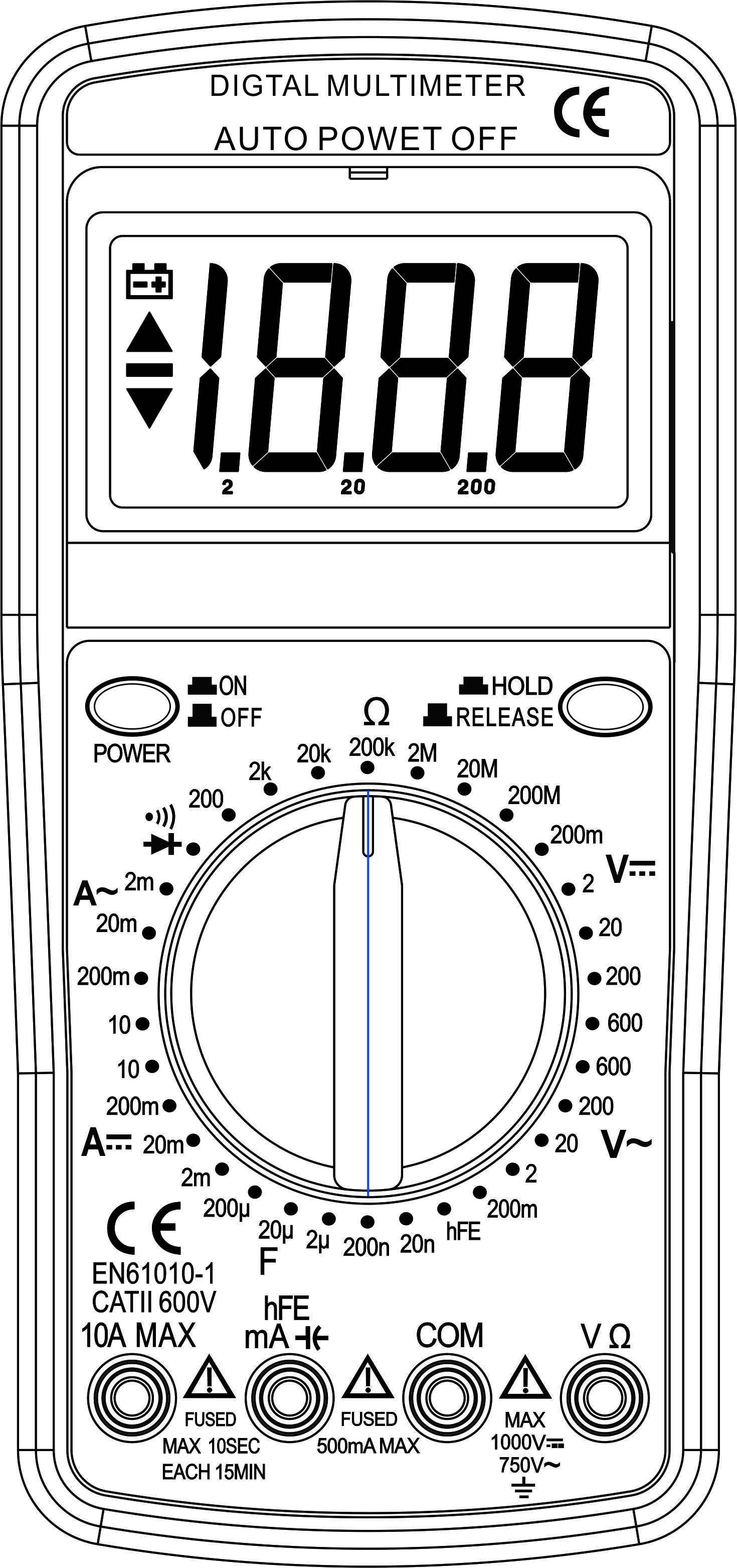
Operating Instructions
Voltage Measurement
Connect red test lead to “VΩ” jack, black lead to “COM” jack.
Set RANGE switch to desired VOLTAGE position, if the voltage to be measured is not known beforehand, set switch to the highest range and reduce it until satisfactory reading is obtained.
Connect test leads to device or circuit being measured.
Turn on power of the device or circuit being measured voltage value will appear on Digital Display along with the voltage polarity.
Please note:
In small range, the meter may display an unstable reading when the test leads have not been connected to the load to be measured. It is normal and will not affect the measurements.
When the meter shows the over range symbol “1”, a higher range must be selected.
To avoid damage to the meter, don’t measure a voltage which exceeds 600Vdc (for DC voltage measurement) or 600Vac (for AC voltage measurement).
Current Measurement
For reading less than 200mA connect red lead to “mA” and black lead to “COM” (for measurements between 200mA and 10A, connect red lead to “10A”) ensure jacks are fully depressed.
Set the range switch to desired AC or DC position. If the current magnitude to be measured is not known beforehand, set the ranges switch to the highest range position and then reduce it range by range until satisfactory resolution is obtained.
Open the circuit to be measured and connect test leads in SERIES with the load in with current is to measure.
Current reading will be displayed on LCD, for DC current measurement, the polarity of the red probe will also be indicated.
Please note:
When the display shows the over range symbol “1”, a higher range must be selected. In addition “10A” function is designed for intermittent use only.
Resistance Measurement
Connect red lead to “VΩ”, black lead to “COM”.
Set the range switch to desired Ω range.
If the resistance being measured is connected to a circuit, turn off power and discharge all capacitors before measurement.
Connect test leads to circuit being measured.
Read resistance value on Digital Display.
Please note:
For resistance measurements >1MΩ, the meter may take a few seconds to stabilize reading. This is normal for high-resistance measurement.
When the input is not connected, i.e. at open circuit, the symbol “1” will be displayed as an over range indicator.
Capacity Measuremnt
Connect the BLACK test lead to the COM jack and the RED to the mA jack.
Set the Range switch at F position. (NOTE: The polarity of the RED lead is positive “+”)
Connect test leads across the capacitor under measure and be sure the polarity of connection is observed.
Please Note:
To avoid damage to the Meter, disconnect circuit power and discharge all high-voltage capacitors before measuring capacitance. The tested capacitor should be discharged before the testing procedure. Never apply voltage to the input, or serious damage may result.
Continuity Test
Connect the BLACK test lead to the “COM” jack and the RED to the “VΩ” jack (Note: The polarity of the red test lead is positive “+”).
Set the range switch to range
Connect the test leads across the load to be measured.
If the circuit resistance is lower than about 30±20Ω, the built-in buzzer will sound.
Diode Measurement
Connect red lead to “VΩmA”, black lead to “COM”.
Set RANGE switch to “
” position.Connect the red test lead to the anode of the diode to be measured and black test lead to cathode.
The meter will show the approximate forward voltage
of the diode. If the connections are reversed, “1” will be
shown on the display.
Transitor hFE Measurement
Set the range switch to hFE range.
Connect the adapter to the “COM” jack and the “hFE” jack. Don’t reverse the connection.
Identify whether the transistor is NPN or PNP type and locate Emitter, Base and Collector lead. Insert the leads of the transistor to be tested into the proper holes of the transistor test socket of the adaptor.
LCD display will show the approximate hFE value.
Battery and Fuse Relacement
Battery and fuse replacement should only be done after the test leads have been disconnected and power is off.
Loosen screws with suitable screwdriver and remove case bottom.
The meter is powered by a single 9V PP3 battery. Snap the battery connector leads to the terminals of a new battery and reinsert the battery into the case top. Dress the battery leads so that they will not be pinched between the case bottom and case top.
The meter is protected by fuse:
A) mA: F0.5A/600V Fast, Breaking capacity is 10KA,
dimensions are 20 x 5mmØ.
B) 10A: F10A/600V Fast, Breaking capacity is 10KA,
dimensions are 20 x 5mmØ.
Replace the case bottom and reinstall the three screws. Never operate the meter unless the case bottom is fully closed.
Accessories
- Instruction manual
- Set of test leads (red and black)
- 9V PP3 battery
Specification
| Specification | Value |
|---|---|
| Power supply | 9Vdc (1 x PP3 supplied) |
| AC current | 2mA - 10A |
| DC current | 2mA - 10A |
| AC voltage | 200mV - 600V |
| DC voltage | 200mV - 600V |
| Capacitance | 200µF - 20nF |
| Resistance | 200 Ohms - 200M Ohms |
| Test lead length | 660mm |
| Dimensions | 190 x 90 x 33mm |
| Weight | 190g |
Precautions
| CAUTION | ||
| RISK OF ELECTRIC SHOCK DO NOT OPEN | ||
| CAUTION : TO REDUCE THE RISK OF ELECTRIC SHOCK, DO NOT REMOVE COVER (OR BACK) NO USER-SERVICEABLE PARTS INSIDE REFER SERVICING TO QUALIFIED SERVICE PERSONNEL | ||
This symbol indicates that dangerous voltage constituting a risk of electric shock is present within this unit
This symbol indicates that there are important operating and maintenance instructions in the literature accompanying this unit
Safety Notice
- Prior to use, read through this safety guide.
- Pay attention to safety warnings.
- Observe all operating requirements.
- For any items designed for indoor use only, do not operate near water or in humid environments.
- For cleaning, only use a lint-free, dry cloth.
- Install according to the specifications.
- Place away from heat sources or heating appliances.
- During placement, ensure adequate support for the product and access to controls and connectors.
- Do not obstruct any cooling vents or openings and allow adequate space for air flow.
- Use only power connections supplied with the product or suitable equivalents.
- Do not modify the equipment in any way.
- For any mains powered appliances, ensure that the mains voltage is as described in the specifications.
- Keep powered products and batteries away from the reach of children.
- In case of malfunction, water ingress or other damage, consult qualified service personnel.
- Avoid pressure or impact to the housing that may result in damage when transporting or installing this product.
- For any Earthed mains product, ensure that the power supply has a protective Earth connection.
- Keep all packaging materials out of reach of children.
Indoor use only : The "House" symbol identifes electrical equipment designed primarily for indoor use.
Disposal : The "Crossed Wheelie Bin" symbol on the product means that the product is classed as Electrical or Electronic equipment and should not be disposed with other household or commercial waste at the end of its useful life. The goods must be disposed of according to your local council guidelines.
AVSL Group Ltd, Unit 2 Bridgewater Park, Taylor Road, Manchester, M41 7JQ, Unitied Kingdom
AVSL (EUROPE) Ltd, Unit 3D North Point House, North Point Business Park, New Mallow Road, Cork, Ireland