CMC-14
CMC-series Mixing Consoles DSP & USB/PC/BT Player
170.940UK
Introduction
Thank you for choosing a Citronic CMC-series mixer as part of your professional sound system. This product has been developed to provide a wide range of facilities for live and studio sound applications. Please read and keep this manual to achieve the best results from your purchase and avoid damage through misuse.
Console layout
Each CMC-series mixing console has a bank of mono input channels which can accept a balanced microphone input or switchable line/instrument input. There is also a stereo input for playback devices or line level instruments. All preamps have studio grade, low noise architecture for the cleanest possible path throughout the signal chain. Console layout is set out in distinct sections to simplify operation. The following pages are divided up into these stages to explain the details and function of each control.
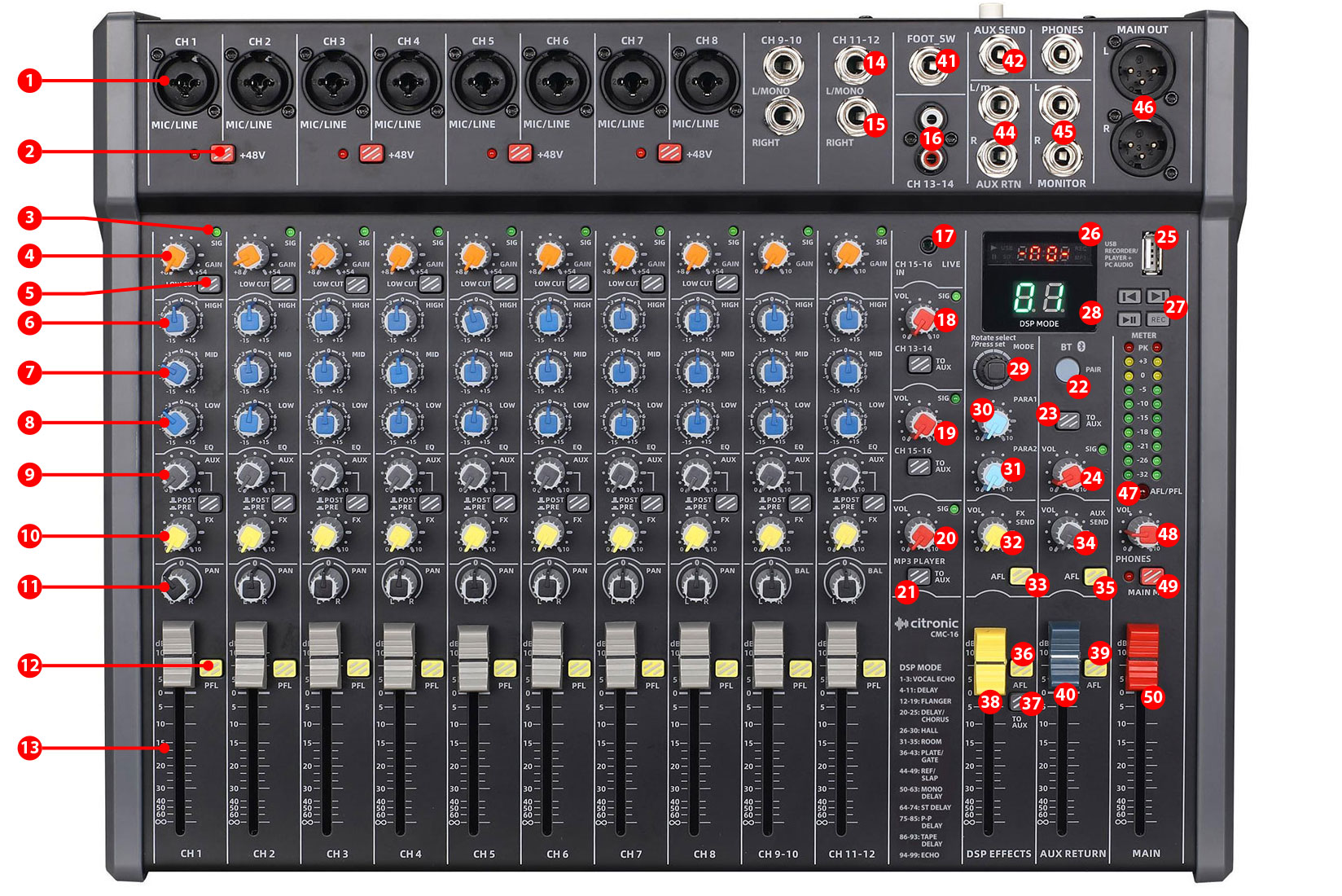
Channel inputs
Channel inputs are provided as XLR or 6.3mm jack on combo sockets. If an XLR is plugged in, this will be connected as low impedance (microphone) level. If a 6.3mm plug is used, this will be connected as high impedance (line) level. The connections for these inputs are assigned as shown below.

Mono input channels
1 Combo input: Connect a balanced microphone via XLR connection or a line level (or instrument) input via 6.3mm plug. An unbalanced XLR can be connected provided that +48V phantom power is not used. Wired as follows.
| Type | Pin 1 / Sleeve | Pin 2 / Tip | Pin 3 / Ring |
|---|---|---|---|
| Balanced | Ground | Signal + | Signal - |
| Unbalanced | Ground | Signal + | Ground |
2 +48V phantom: Press this button in to enable +48V phantom power to the pair of XLRs and the LED indicator will light. This provides power to some condenser microphones and DI boxes. Do not use phantom power with unbalanced XLR connectors. (this doesn’t affect any 6.3mm inputs)
Channel controls
3 SIG LED: A green indicator LED which illuminates when the signal is present
4 GAIN: Adjust this to match the input signal level to be suitable for the channel. Increase this setting if the input source is quiet.Reduce this setting if the channel is overloading or sounds distorted.
5 LOW CUT: Preset filter for removing the lowest frequencies on microphones to avoid handling noise or pops from close vocals.
6 HIGH EQ: This control can boost or cut the high frequencies by ±15dB (12 o’clock position is zero)
7 MID EQ: This control can boost or cut the mid frequencies by ±15dB (12 o’clock position is zero)
8 LO EQ: This control can boost or cut the mid frequencies by ±15dB (12 o’clock position is zero)
9 AUX: This control regulates the amount of the channel signal that is fed to the DSP effects section, varying the amount of effect.
10 FX: This control regulates the amount of the channel signal that is fed to the DSP effects section, varying the amount of effect.
11 PAN: Sets the position of the mono input channel within the stereo field. Adjustable to the left or right of the mix with the “0” setting for centre.
12 PFL: Pre-Fader Listen when pressed in sends the channel direct to the monitoring section for level setting and signal checking.
13 VOL: Rotary volume control for the mono or stereo input channel.
Stereo Inputs
14 L/MONO: Line level 6.3mm jack input. Left side of the stereo input, or will default to mono if connected alone (i.e. without a right-side input)
15 RIGHT: Line level 6.3mm jack input for right side of stereo input.
16 RCA L+R: Additional stereo line input channel on RCA connection.
17 LIVE: 3.5mm stereo line (or aux) input for mp3 player, smart phone etc.
18 VOL: Rotary Volume control for RCA line channel with signal LED.
19 VOL: Rotary Volume control for LIVE 3.5mm input with signal LED.
MP3 Player
CMC-series mixers have an inbuilt USB mp3 audio player/recorder and Bluetooth receiver.
20 MP3 VOL: Volume control for USB mp3 playback with signal LED.
21 TO AUX: Routes the MP3 player output to the Auxiliary bus.
22 BT PAIR: Press this button to activate the Bluetooth receiver. (see below Operation section for pairing procedure)
23 TO AUX: Routes the Bluetooth receiver output to the Auxiliary bus.
24 VOL: Volume control for the Bluetooth receiver with signal LED
25 USB port: Connect USB flash drive to play or record tracks on the media. Connecting to a PC using a USB A to A lead will present the mp3 input and main output as a 2-way stereo plug & play USB audio interface. This should appear in your PC software as an input/output option.
26 Display: The top part of the LED display shows USB playback or record status and time.
27 Controls: 4 button control panel for track playback and recording. (recorded tracks are stored on the USB flash drive as numbered files)
| Symbol | Function |
|---|---|
| ⏮ | Previous track |
| ⏭ | Next track |
| ▶⏸ | Play/Pause |
| REC | Record |
DSP Effects
28 Display: The lower part of the LED display shows the DSP preset number & MAIN OUT VU meter
29 MODE selector: Rotate until required preset is shown and press to select that preset
30 PARA1: Parameter 1 of the preset - see appendix (the adjusted value is stored for that preset)
31 PARA2: Parameter 2 of the preset - see appendix (the adjusted value is stored for that preset)
32 FX SEND: Adjusts the level of signal fed to the DSP FX section
33 AFL: After Fader Listen routes FX send output to the monitor section when pressed in.
34 AUX SEND: Adjusts the level of AUX mix fed out of the AUX SEND output
35 AFL: 30. After Fader Listen routes output of AUX mix to the monitor section when pressed in.
36 AFL: 30. After Fader Listen routes FX output to the monitor section when pressed in.
37 To AUX: Routes FX output to the AUX bus.
38 DSP EFFECTS: After Fader Listen routes AUX return to the monitor section when pressed in.
39 AFL: After Fader Listen routes AUX return to the monitor section when pressed in.
40 AUX RETURN: AUX RETURN level control.
Output Section
41 FOOT SW: FX mute footswitch input (momentary).
42 AUX SEND: Output of AUX bus from all channels.
43 PHONES: Connect Headphones via 6.3mm stereo jack (32Ω min).
44 AUX RTN: L+R return inputs for AUX loop.
45 _ MONITOR_: L+R monitor line outputs.
46 MAIN OUT: L+R Balanced XLR main line outputs.
47 AFL / PFL: Indicator lit when channels or other sources are selected to AFL (after-fader listen) or PFL (pre-fader listen).
48 PHONES: Rotary volume control for PHONES and MONITOR outputs.
49 MAIN MUTE: Mutes main outputs when pressed in.
50 MAIN OUT: Main output volume fader.
Setting Up
Connect microphones to the Mic / Line / Instrument combo inputs (1) via XLR, ensuring that the +48V button (2) is pressed in for any condenser microphones or D.I. boxes that require phantom power to operate (the +48V button activates phantom power to XLR inputs in pairs. If a microphone does not require phantom power, enabling it will not damage the microphone, but you must ensure that the XLR is wired as a balanced connection. i.e. separate +, -, and GND connections to avoid damage to the mixer)
For line inputs (such as CD, mp3 player, laptop, digital keyboard etc.) or instrument inputs (such as electric guitar), connect these via 6.3mm jack plug to the combo inputs (1)
For stereo line level signals, such as CD or mp3 players, computer sound cards or electronic keyboards, connect these via 6.3mm jack plug to the stereo inputs (14, 15) or if the input device is mono, just connect to the L/MONO input (14). The stereo channel has its own volume control (17)
Further stereo line inputs are provided on RCA or 3.5mm jack (16, 17) governed by separate volume controls (18, 19)
If headphones are to be used for monitoring the main output, connect these to the PHONES 6.3mm stereo jack (43) and turn the PHONES control (48) down fully before listening to the headphones, gradually turning this control up to the required level to avoid damage to hearing.
A mono AUX SEND output (42) may be used to feed outboard audio processors, such as effects machines, or as a separate monitor mix feed and controlled by the AUX SEND volume control (34). AUX RTN (44) is a L+R pair of return inputs for feeding outboard equipment connected from the AUX send feed or as a separate stereo input, governed by the AUX RTN volume control (40)
FX SEND (32) is an overall volume control of all channels mixed into the DSP effects section, which should be set to avoid clipping or excessive noise, whilst the DSP EFFECTS fader (38) controls the level of effects to main outputs. This can also be routed to the AUX section by pressing in TO AUX (37)
The FX SEND, AUX SEND, DSP EFFECTS, or AUX RETURN signals can also be routed to the monitor section by pressing in respective the AFL button (33, 35, 36, 39)
Active monitor speakers or recording equipment may be fed from the L+R MONITOR jacks (45)
Connect the MAIN OUT L + R XLR outputs (46) to the receiving amplifier or recording device.
Finally, connect the rear IEC inlet to a suitable mains outlet for power, ensuring correct supply voltage and that the circuit is earthed.
Before switching power on, it is advised to turn all volume controls fully down to avoid any loud noises through the connected speakers or recording equipment.
Operation
Set the MAIN OUT control (50) fully down, switch on the POWER at the rear and the display will light.
Check the output of any channel by starting with its VOL (13), AUX (9) and FX (10) set fully down.
HIGH, MID and LOW EQ controls (6, 7, 8) should all be set in the mid position (12 o’clock). Make sure MAIN MUTE (49) is not pressed in and turn up the MAIN OUT or PHONES (50, 48) part way up and listen whilst playing the signal (or speaking into the microphone) and increasing its VOL control gradually. Stop when the desired output level is reached. Avoid aiming the microphone or instrument pickup towards the loudspeaker(s), which can cause feedback, which is a loud whistling or howling sound caused when a mic or pickup hears its own output.
To adjust the tone characteristics of a Mic, Line or Instrument input signal, the high, mid and low frequency content can be individually cut or boosted using the HIGH, MID and LOW EQ controls (6, 7, 8).
Turning the HIGH control clockwise from 12 o’clock boosts the high frequencies (treble) for a brighter sound and turning it anticlockwise cuts them for a duller sound.
Turning the MID control clockwise from 12 o’clock boosts the middle frequencies (mid) for a more prominent sound and turning it anticlockwise cuts them for a less intrusive sound.
Turning the LOW control clockwise from 12 o’clock boosts the low frequencies (bass) for a thicker sound and turning it anticlockwise cuts them for a thinner sound.
Boosting these too much can increase the chance of feedback, whereas cutting can sometimes help to reduce feedback, so experimentation is often necessary.
Adding some DSP presets to a mic or instrument can create a spatial or rotating effect. To add the effect, move the DSP EFFECTS fader up (38) and gradually increase the FX control (10) on the input channel.
There are 99 pre-set types available by rotating and pressing the MODE selector (29) including digital reverbs, delays and modulation effects. Each effect has 2 adjustable parameters (30, 31) to enable you to tailor the effect as required. Experimentation is advised to achieve the best results from this section.
See the previous “DSP Effects” controls description and the appendix for details about the DSP effects.
If a smart phone or tablet is to be connected as a wireless music source, press the BT PAIR button (22) and it will flash blue rapidly.
Search on the smart phone or tablet for a device called “Citronic” and select to connect for audio playback. The BT PAIR button (22) will be lit blue constantly when paired successfully.
When a track is being, the BT PAIR button will flash slowly. Turn up the BT VOL control (24) to hear the track being played. This can also be routed to the AUX buss by pressing in TO AUX (23). Pressing the BT PAIR button again will disable the Bluetooth receiver.
The USB player/recorder section will playback mp3 or wma files stored on a USB flash drive. If the content does not play automatically, press the Play/Pause button.
Pressing the Play/Pause button during playback will pause the current track until it is pressed again.
Use the Previous track and Next track buttons to navigate through tracks stored on the USB media.
Pressing the REC (record) button arms the CMC mixer to record to the USB media.
Press Play/Pause to begin recording and press again to pause or press REC to stop recording.
Any recorded tracks are stored on the USB flash drive as numbered audio files, which can be played back like the other files that are stored on the flash drive.
This same USB port can be used to connect to a PC or Mac computer using a USB-A to USB-A lead. When connected, the computer will see the CMC mixer as a generic USB audio interface.
Set this USB audio device as the input source in order to play audio into the computer DAW software.
Likewise, setting it as the output device will enable the audio output from the computer to play directly into the main stereo bus of the CMC mixer.
Turn down the volume controls before powering down to avoid loud noises through connected equipment.
Unplug from the mains if not being used for long periods of time.
DSP Effects Presets & Parameters
| No | Name | Para 1 | Para 2 |
|---|---|---|---|
| 1 | KTV Echo 3 | Dly Time | Decay Time |
| 2 | KTV Echo 2 | Dly Time | Decay Time |
| 3 | KTV Echo 1 | Repeat | Decay Time |
| 4 | Bright Hall Mid | Pre-Delay | Decay Time |
| 5 | Bright Room Mid | Pre-Delay | Decay Time |
| 6 | Plate Mid | Pre-Delay | Decay Time |
| 7 | Mono Delay 220 | Repeat | Delay Time |
| 8 | Stereo Delay 220 | Repeat | Delay Time |
| 9 | Ping Pong Delay 220 | Repeat | Delay Time |
| 10 | Tape Delay 220 | Repeat | Delay Time |
| 11 | Modulation Delay | Depth | Delay Time |
| 12 | Chorus Slow | Depth | Speed |
| 13 | Chorus Fast | Depth | Speed |
| 14 | Flanger Light | Depth | Speed |
| 15 | Flanger Heavy | Depth | Speed |
| 16 | Distortion FX | Drive | Gain |
| 17 | Wah Wah | Depth | Speed |
| 18 | Tremolo | Depth | Speed |
| 19 | Pitch Shift | Cent | Key |
| 20 | Chorus + Room | Speed | Decay Time |
| 21 | Chorus + Hall | Speed | Decay Time |
| 22 | Delay + Chorus | Speed | Delay Time |
| 23 | Delay + Flanger | Speed | Delay Time |
| 24 | Delay + Chorus + Room | DlyTime | Decay Time |
| 25 | Delay + Chorus + Hall | DlyTime | Decay Time |
| 26 | Bright Hall Small | Pre-Delay | Decay Time |
| 27 | Bright Hall Large | Pre-Delay | Decay Time |
| 28 | Warm Hall Small | Pre-Delay | Decay Time |
| 29 | Warm Hall Mid | Pre-Delay | Decay Time |
| 30 | Warm Hall Large | Pre-Delay | Decay Time |
| 31 | Bright Room Small | Pre-Delay | Decay Time |
| 32 | Bright Room Large | Pre-Delay | Decay Time |
| 33 | Warm Room Small | Pre-Delay | Decay Time |
| 34 | Warm Room Mid | Pre-Delay | Decay Time |
| 35 | Warm Room Large | Pre-Delay | Decay Time |
| 36 | Plate Small | Pre-Delay | Decay Time |
| 37 | Plate Large | Pre-Delay | Decay Time |
| 38 | Reverb + Gate Short | Gate Time | Decay Time |
| 39 | Reverb + Gate Mid | Gate Time | Decay Time |
| 40 | Reverb + Gate Long | Gate Time | Decay Time |
| 41 | Doubling Small | DlyTime | Decay Time |
| 42 | Doubling Mid | DlyTime | Decay Time |
| 43 | Doubling Large | DlyTime | Decay Time |
| 44 | Early Reflections Small | Pre-Delay | Decay Time |
| 45 | Early Reflections Mid | Pre-Delay | Decay Time |
| 46 | Early Reflections Large | Pre-Delay | Decay Time |
| 47 | Slap Short | None | Delay Time |
| 48 | Slap Mid | None | Delay Time |
| 49 | Slap Long | None | Delay Time |
| 50 | Mono Delay 60 | Repeat | Delay Time |
| 51 | Mono Delay 100 | Repeat | Delay Time |
| 52 | Mono Delay 150 | Repeat | Delay Time |
| 53 | Mono Delay 300 | Repeat | Delay Time |
| 54 | Mono Delay 500 | Repeat | Delay Time |
| 55 | Mono Delay 600 | Repeat | Delay Time |
| 56 | Mono Delay 800 | Repeat | Delay Time |
| 57 | Mono Delay 1000 | Repeat | Delay Time |
| 58 | Mono Delay 1200 | Repeat | Delay Time |
| 59 | Mono Delay 1400 | Repeat | Delay Time |
| 60 | Mono Delay 1800 | Repeat | Delay Time |
| 61 | Mono Delay 2500 | Repeat | Delay Time |
| 62 | Mono Delay 3000 | Repeat | Delay Time |
| 63 | Mono Delay 3500 | Repeat | Delay Time |
| 64 | Stereo Delay 60 | Repeat | Delay Time |
| 65 | Stereo Delay 100 | Repeat | Delay Time |
| 66 | Stereo Delay 150 | Repeat | Delay Time |
| 67 | Stereo Delay 300 | Repeat | Delay Time |
| 68 | Stereo Delay 500 | Repeat | Delay Time |
| 69 | Stereo Delay 600 | Repeat | Delay Time |
| 70 | Stereo Delay 800 | Repeat | Delay Time |
| 71 | Stereo Delay 1000 | Repeat | Delay Time |
| 72 | Stereo Delay 1200 | Repeat | Delay Time |
| 73 | Stereo Delay 1400 | Repeat | Delay Time |
| 74 | Stereo Delay 1800 | Repeat | Delay Time |
| 75 | Ping Pong Delay 60 | Repeat | Delay Time |
| 76 | Ping Pong Delay 100 | Repeat | Delay Time |
| 77 | Ping Pong Delay 150 | Repeat | Delay Time |
| 78 | Ping Pong Delay 300 | Repeat | Delay Time |
| 79 | Ping Pong Delay 500 | Repeat | Delay Time |
| 80 | Ping Pong Delay 600 | Repeat | Delay Time |
| 81 | Ping Pong Delay 800 | Repeat | Delay Time |
| 82 | Ping Pong Delay 1000 | Repeat | Delay Time |
| 83 | Ping Pong Delay 1200 | Repeat | Delay Time |
| 84 | Ping Pong Delay 1400 | Repeat | Delay Time |
| 85 | Ping Pong Delay 1800 | Repeat | Delay Time |
| 86 | Tape Delay 60 | Repeat | Delay Time |
| 87 | Tape Delay 100 | Repeat | Delay Time |
| 88 | Tape Delay 150 | Repeat | Delay Time |
| 89 | Tape Delay 300 | Repeat | Delay Time |
| 90 | Tape Delay 500 | Repeat | Delay Time |
| 91 | Tape Delay 600 | Repeat | Delay Time |
| 92 | Tape Delay 800 | Repeat | Delay Time |
| 93 | Tape Delay 1000 | Repeat | Delay Time |
| 94 | Echo 1 100 | Repeat | Delay Time |
| 95 | Echo 1 400 | Repeat | Delay Time |
| 96 | Echo 2 100 | DlyTime | Decay Time |
| 97 | Echo 2 400 | DlyTime | Decay Time |
| 98 | Echo 3 100 | DlyTime | Decay Time |
| 99 | Echo 3 400 | DlyTime | Decay Time |
Precautions
Disposal : The "Crossed Wheelie Bin" symbol on the product means that the product is classed as Electrical or Electronic equipment and should not be disposed with other household or commercial waste at the end of its useful life. The goods must be disposed of according to your local council guidelines.
AVSL Group Ltd, Unit 2 Bridgewater Park, Taylor Road, Manchester, M41 7JQ, Unitied Kingdom
AVSL (EUROPE) Ltd, Unit 3D North Point House, North Point Business Park, New Mallow Road, Cork, Ireland