CL22
Stereo Compressor / Limiter / Gate
170.935UK
Introduction
Thank you for choosing this Citronic compressor-limiter. This product has been designed to give accurate dynamics control to a wide range of audio systems. In order to achieve the best results from this equipment and avoid damage through misuse, please read and follow these instructions and retain for future reference.
Features
- Variable expander/gate per channel
- Variable enhancer per channel
- Dual mono or stereo link modes
- Manual or auto attack & release
- Gain reduction and level meters
- External detection loop per channel
- Balanced connections
Warning:
To prevent the risk of fire or electric shock, do not expose any part of the unit to rain or moisture. If liquids are spilled on the surface, stop using immediately, allow unit to dry out and have checked by qualified personnel before further use. Avoid impact, extreme pressure or heavy vibration to the unit. There are no user serviceable parts inside the compressor-limiter – refer all servicing to qualified service personnel.
Safety
- Check that the supplied mains lead is in good condition and the supply voltage is correct.
- Ensure signal leads are of good condition and connected to appropriate inputs/outputs.
- Do not allow any foreign particles to enter the unit through control apertures or connector apertures.
Placement
- Keep out of direct sunlight and away from heat sources.
- Keep away from damp or dusty environments.
- When rack-mounting, avoid placing heavy units above the unit and ensure all connectors and controls are accessible
Cleaning
- Use a soft cloth with a neutral detergent to clean the casing as required.
- Use a soft brush to clear debris from the control surface.
- Do not use strong solvents for cleaning the unit.
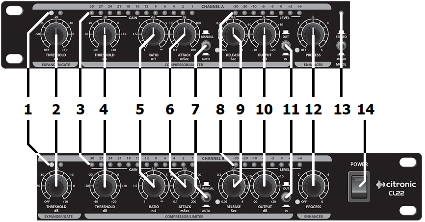
Front Panel
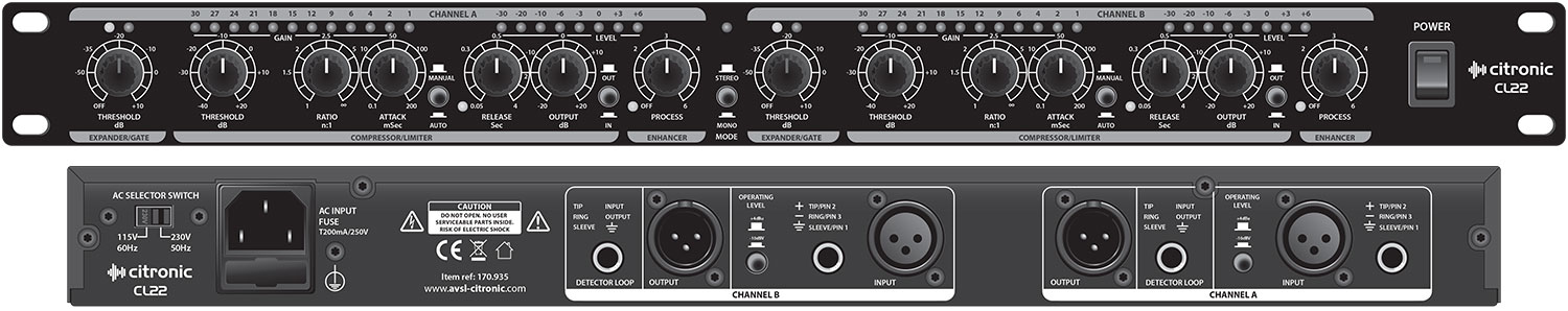
Rear Panel
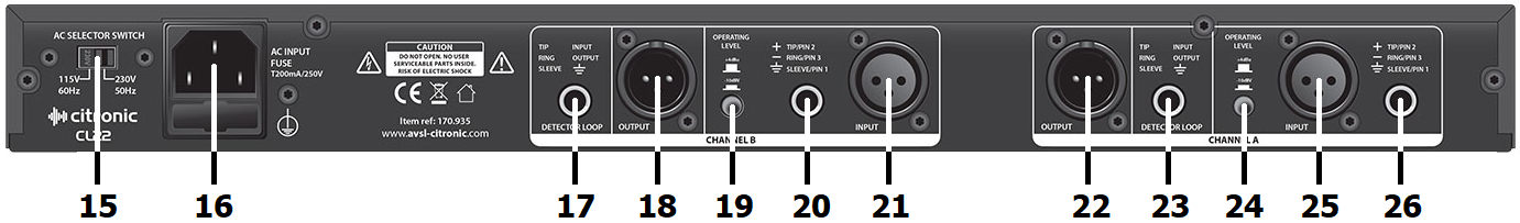
- Voltage selector
- IEC mains inlet
- DETECTOR LOOP insert jack: Channel B
- OUTPUT XLR: Channel B
- OPERATING LEVEL switch: Channel B
- INPUT jack: Channel B
What is a Compressor-Limiter?
A compressor-limiter is a device for controlling the “dynamic range” of an audio signal.
The dynamic range is how we describe the variance between quiet and loud passages of audio.
For example, a snare drum has a very dramatic, loud attack which dies out to quiet very quickly, whereas a note played on a violin has a fairly constant moderate sound level – these have very different “dynamics”.
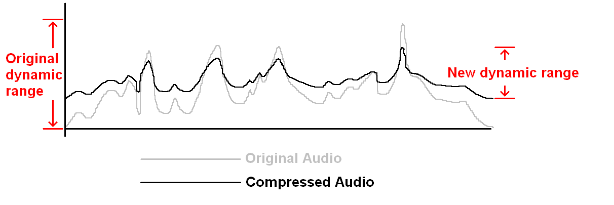
Sometimes we would like to be able to make quiet passages less quiet and loud passages less loud – this is called “compressing” the dynamic range. The following graph shows how audio level over time is affected by compression of a ratio 2:1
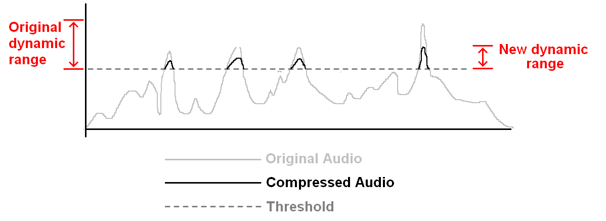
It may be preferred to maintain the quieter passages of audio unaffected and only apply the compression at the highest volume levels, set by a “Threshold” parameter. This is known as “Limiting” and can be useful to control maximum sound levels for safety of listeners and to protect audio equipment.
Since compression or limiting can allow the lower frequencies to be emphasised, an ENHANCER processor is added, which when turned up, helps to restore the balance of higher frequencies.
In addition to these functions, the Citronic CL22 has an EXPANDER/GATE for each channel. When there is a period of silence in audio, often there is low level noise from RF interference, circuitry noise or mains hum. The EXPANDER/GATE section cuts out the audio below a set volume level to eliminate these unwanted noises when the audio should be silent.
Connection
The CL22 can be used either as 2 independent mono compressor/limiters (e.g. for channel inserts on vocal microphones) or as the main stereo compressor/limiter for a sound system or recording setup.
When the CL22 is to be used to control the main stereo mix, it should be connected via the master inserts on the mixer or between the mixer and power amplifier/recording device. If settings for each side of the stereo are to be identical, the STEREO LINK button can be pressed in and all settings for Channel A will apply to Channel B and controls for Channel B will be ineffective.
Connect the L+R outputs from the mixer or insert sends to the Channel A and Channel B inputs of the CL22 using good quality XLR or 6.3mm jack leads (balanced or unbalanced). Select the correct operating level (+4dBu or -10dBV) for high or low impedance type signals via the OPERATING LEVEL switches on the rear panel.
Connect the L+R outputs from the CL22 to the amplifier/recording device inputs or insert returns. Connect mains via the supplied IEC, ensuring that the voltage selector is the same as supply voltage.
In certain scenarios, it may be preferred to make the compressor respond to the volume of an external signal (e.g. to duck the audio when a vocal announcement is detected). Plugging an external control signal into the DETECTOR LOOP via mono 6.3mm jack will achieve this effect.
Alternatively, in some cases, it may be desired to reduce volume only when the high frequencies are loud. This can be useful to reduce volume of “sibilance” (the “S” and “T” sounds of a vocal passage) and can be achieved by placing a high pass filter win the DETECTOR LOOP using an insert lead (TRS jack to 2 x mono jack).
The Ring connection carries the SEND of the loop and the TIP carries the RETURN of the loop, both sharing a common ground or earth. The compressor becomes a “De-esser” in this configuration.
Operation
With amplifiers turned down, power up the CL22 and set all controls to
the default position as follows…
Turn the EXPANDER/GATE THRESHOLD to “OFF”, Set COMPRESSOR THRESHOLD to
“0”, ratio to “1” and OUTPUT to “0”.
The ENHANCER should be set to “OFF” and STEREO LINK set depending upon
the configuration (stereo or dual mono)
Play the audio signal to be processed and gradually turn up the amplifier/recording device. Audio should now be heard unaffected.
Press the IN/OUT button in and increase the COMPRESSOR RATIO to the
desired level (lower numbers are milder effect)
Bringing the COMPRESSOR THRESHOLD down from “0” should increase the
amount of signal affected. Setting the THRESHOLD to -40dB effectively
compresses the entire signal, whereas higher THRESHOLD settings are
classed as Limiting.
The amount of effect can be checked on the GAIN REDUCTION indicators and by pressing the IN/OUT buttons for comparison.
If MANUAL mode is selected, altering ATTACK and RELEASE will give different timing to the effect at the beginning and end of each triggered compression. Alternatively, AUTO mode can vary this to suit the signal type automatically.
(e.g. vocals and drums will suit different settings)
If the GAIN REDUCTION indicators show a lot of compression, it is wise to gently increase the OUTPUT to compensate and bring the signal up to the level required (this is known as “make-up gain”)
If the signal becomes “boomy” through heavy compression, high frequencies can be restored by turning up the ENHANCER PROCESS control.
To eliminate noise in silent passages, stop any audio passing through the CL22 and gradually turn up the EXPANDER GATE THRESHOLD.
Stop turning the THRESHOLD control when the background noise (hiss or hum) disappears. This process is gradual and may be adjusted so as not to interfere with very quiet passages of wanted audio.
Remember to turn down amplifiers and switch off prior to powering down the compressor-limiter to avoid loud noises in the sound system.
Troubleshooting
| No function and Power switch LED is not lit | Ensure mains voltage is correct (check selector) and connected properly |
| Ensure front panel power switch and mains outlet switch are on | |
| Power is on but no audio output | Check XLR and jack leads are OK and connected properly |
| Check that OUTPUT controls are not turned fully down | |
| Check that inputs and outputs are connected the correct way around | |
| Check that LOW out is not connected to amp for mid-high cabs in error | |
| Unplug jacks from DETECTOR LOOP to check if connected wrongly | |
| Turn down EXPANDER/GATE THRESHOLD if set too high | |
| Distorted output | Reduce OUTPUT controls |
| Check equipment connected to DETECTOR LOOP is not set wrongly | |
| Check ENHANCER PROCESS control is not set too high | |
| Make sure OPERATING LEVEL switches are set to the correct “dB” | |
| Output is very low level | Increase OUTPUT level |
| Increase COMPRESSOR THRESHOLD and reduce RATIO if too high | |
| Check equipment connected to DETECTOR LOOP is not set wrongly | |
| Make sure OPERATING LEVEL switches are set to the correct “dB” |
Specification
| Specification | Value |
|---|---|
| Power supply | 115/230Vac, 50/60Hz (IEC) |
| Connectors : bal/unbal | XLR or 6.3mm jack inputs and outputs L+R |
| Input impedance : balanced | 50k Ohms |
| Input impedance : unbalanced | 25k Ohms |
| Output impedance | 60 Ohms |
| Operating level | +4dBu/-10dBV, switchable |
| Frequency response | 20Hz-20kHz (+0/-0.5dB) |
| Signal to noise ratio | >95dBu |
| Crosstalk | <100dB |
| THD | 0.04% @ +4dBu 1kHz |
| Dimensions | 482 x 44 x 180mm |
| Weight | 3.2kg |
Precautions
| CAUTION | ||
| RISK OF ELECTRIC SHOCK DO NOT OPEN | ||
| CAUTION : TO REDUCE THE RISK OF ELECTRIC SHOCK, DO NOT REMOVE COVER (OR BACK) NO USER-SERVICEABLE PARTS INSIDE REFER SERVICING TO QUALIFIED SERVICE PERSONNEL | ||
This symbol indicates that dangerous voltage constituting a risk of electric shock is present within this unit
This symbol indicates that there are important operating and maintenance instructions in the literature accompanying this unit
Safety Notice
- Prior to use, read through this safety guide.
- Pay attention to safety warnings.
- Observe all operating requirements.
- For any items designed for indoor use only, do not operate near water or in humid environments.
- For cleaning, only use a lint-free, dry cloth.
- Install according to the specifications.
- Place away from heat sources or heating appliances.
- During placement, ensure adequate support for the product and access to controls and connectors.
- Do not obstruct any cooling vents or openings and allow adequate space for air flow.
- Use only power connections supplied with the product or suitable equivalents.
- Do not modify the equipment in any way.
- For any mains powered appliances, ensure that the mains voltage is as described in the specifications.
- Keep powered products and batteries away from the reach of children.
- In case of malfunction, water ingress or other damage, consult qualified service personnel.
- Avoid pressure or impact to the housing that may result in damage when transporting or installing this product.
- For any Earthed mains product, ensure that the power supply has a protective Earth connection.
- Keep all packaging materials out of reach of children.
Disposal : The "Crossed Wheelie Bin" symbol on the product means that the product is classed as Electrical or Electronic equipment and should not be disposed with other household or commercial waste at the end of its useful life. The goods must be disposed of according to your local council guidelines.
AVSL Group Ltd, Unit 2 Bridgewater Park, Taylor Road, Manchester, M41 7JQ, Unitied Kingdom
AVSL (EUROPE) Ltd, Unit 3D North Point House, North Point Business Park, New Mallow Road, Cork, Ireland