

UVB-24X
UVB-24X: 24 x 3W UV LED Bar DMX
160.053UK
About this manual
This manual provides essential information for installing, operating, and maintaining your product. Please read and keep this manual to ensure the best performance from your purchase and to avoid damage resulting from improper use.
Introduction
Thank you for choosing the UVB-24X UV LED bar unit. Please read this manual prior to use to avoid damage to the item. This versatile UV LED Bar is packed with features in a compact, manageable enclosure and is suitable for a wide array of applications ranging from Bar and nightclub Installations to Mobile DJ setups.
Safety information
This section contains important safety instructions that must be followed to reduce the risk of injury, damage to the product, or damage to other equipment. Read all safety information before installing, operating, or servicing the product. Failure to follow these instructions may result in personal injury, property damage, or impaired product performance.
Warning
- To prevent the risk of fire or electric shock, do not expose any of the components to rain or moisture.
- If liquids are spilled on any component, stop using immediately, allow unit to dry out and have checked by qualified personnel before further use.
- Avoid impact or heavy vibration to any of the components.
- No user serviceable parts inside.
- Refer servicing to qualified service personnel.
Placement
- Keep the unit out of direct sunlight and away from heat sources.
- Keep the unit away from moisture or dusty environments.
- Allow adequate space for cooling around the unit.
- Do not place heavy objects on top of the unit.
Cleaning
- Use a soft cloth with a neutral detergent to clean the housing as required.
- A soft brush can be used to clear debris from the unit without damaging it.
- Do not use solvents for cleaning the unit.
Controls and features
Front Panel
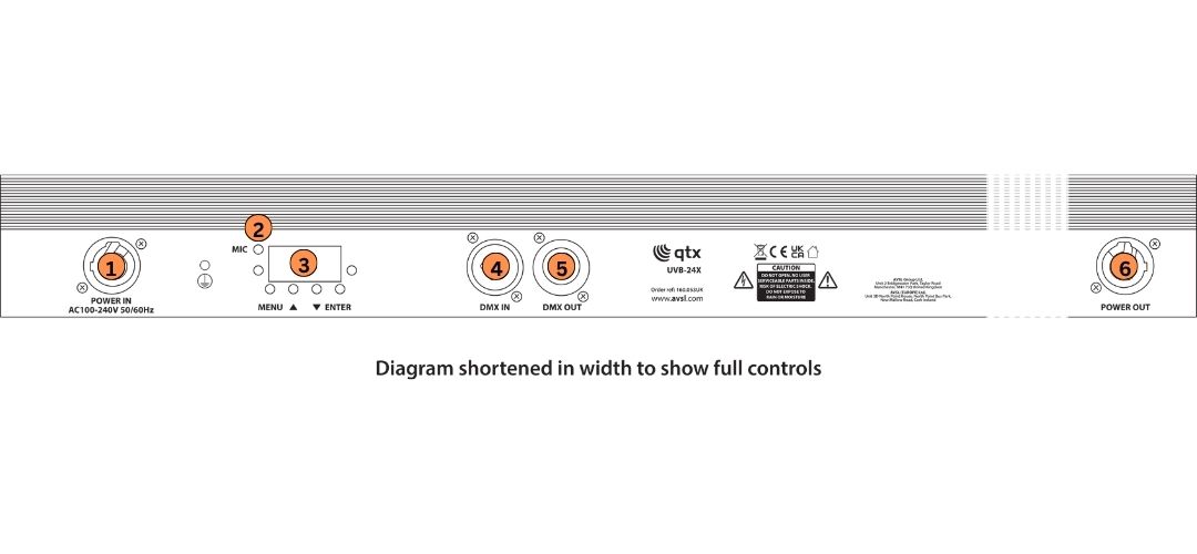
1. Power Inlet
2. Internal Microphone
3. Display
4 DMX In
5 DMX Out
6 Power Outlet
Power requirements
- Power supply: 100–240 Vac, 50/60 Hz.
- Use only the supplied or approved power adapter.
Installation and setup
1. Unpack the unit and verify all supplied components are present.
2. Place the unit on a stable, level surface or attach to clamp.
3. Connect required cables as described below.
4. Apply power (if applicable).
Operation
Basic menu operation
Press the Menu button to enter the settings Menu.
Press the Up and Down buttons to navigate through the various setting functions.
Press the Enter button to confirm the desired setting.
| Menu | Options and Settings | Description |
|---|---|---|
| d001 | 001–512 | DMX Address (4CH Mode) |
| A001 | 001–512 | DMX Address (4CH Mode) |
| r255 | 000-255 | Section 1 Dimmer |
| G255 | 000-255 | Section 2 Dimmer |
| b255 | 000-255 | Section 3 Dimmer |
| u255 | 000-255 | Section 4 Dimmer |
| FH01 | 01-99 | Strobe Slow-Fast |
| CL01 | 01-08 | Strobe Macro |
| CC01 | 01-99 | Program Jump Speed Slow - Fast |
| DE01 | 01-99 | Program Fade Speed Slow-Fast |
| CP99 | 01-99 | Pulse Effect Slow-Fast |
| Su01 | 01-09 | Sound Activated Mode |
DMX Operation
Channel Mode Selection
Before selecting you DMX address please select one of the following to confirm DMX channel mode.
- d001= 4 Ch Mode
- A001= 8 Ch Mode
DMX Address Setting
1. Press the Menu button until either d001/A001 is displayed and press Enter.
2. Press the Up or Down buttons to find your desired address. Press Enter to set your desired DMX address
DMX Traits
4 Channel Mode
| 4 CH | Setting | DMX Value | Function |
|---|---|---|---|
| CH 1 | Dimmer | 000–255 | Section 1 LEDs |
| CH 2 | Dimmer | 000–255 | Section 2 LEDs |
| CH 3 | Dimmer | 000–255 | Section 3 LEDs |
| CH 4 | Dimmer | 000–255 | Section 4 LEDs |
8 Channel Mode
| 8 CH | Setting | DMX Value | Function |
|---|---|---|---|
| CH 1 | Dimmer | 000–255 | Global Dimmer |
| CH 2 | Dimmer | 000–255 | Section 1 LEDs |
| CH 3 | Dimmer | 000–255 | Section 2 LEDs |
| CH 4 | Dimmer | 000–255 | Section 3 LEDs |
| CH 5 | Dimmer | 000–255 | Section 4 LEDs |
| CH 6 | Strobe | 000–255 | Slow-Fast |
| CH 7 | Macros | 000–255 | Slow-Fast |
| CH 8 | Macros Speed | 000–255 | Slow-Fast |
Maintenance
- Regular maintenance is required to ensure the product’s longevity.
- Inspect cables and connectors periodically.
Troubleshooting
If the unit does not operate as expected, consult the table below before contacting technical support. Many common issues can be resolved by checking connections, power sources, or settings.
Before proceeding
- Ensure the unit is installed and operated according to this manual.
- Verify that all connections are secure.
- Restore the unit to its default or minimum configuration before troubleshooting.
Before any maintenance
- Switch off the unit and disconnect it from the power source (if applicable).
- Allow the unit to cool before handling.
- Do not remove covers or attempt internal repairs.
Common issues
The following table lists common issues and corrective actions that do not require opening the unit.
| Fault | Test Notes |
|---|---|
| No power ( mains) | Check mains voltage is correct and outlet is switched on |
| " | Check lead and fuse |
| No Light Output | Check Unit is set to Manual,Auto or Sound Mode if being used Stand Alone |
| " | Check DMX settings from controller (dimmer levels, blackout) |
| Unresponsive to DMX | Check the unit is set to the correct DMX Address |
| " | Check the unit is set to the correct DMX Channel Mode |
| " | Check DMX Connection and Leads |
| " | Check DMX Controller is not Set to Blackout |
| " | Check DMX Controller is set to the correct fixture |
| Overheating/Cutting Out | Ensure adequate ventilation and unit is not too close to a heat source |
Disposal and recycling
Dispose of this product in accordance with local environmental regulations. Do not dispose of electronic equipment with household waste.
Compliance
This product complies with applicable safety and EMC standards.
Specification
| Specification | Value |
|---|---|
| LED : type | 24 x 3w UV LEDs |
| Ultraviolet wavelength | 398nm |
| Beam angle | 60° |
| Modes | Auto, Sound, Master/Slave,DMX512 and RDM |
| DMX channels | 4Ch or 8 Ch |
| DMX connection | 3 Pin DMX (In/Out) |
| Power connection | Twist and Lock In/Out |
| Power : input | AC100-240V 50/60Hz |
| Power consumption | 54w |
| Dimensions | 1065mm x 86mm x 60mm (W/Bracket) |
| Weight | 2kg |
Precautions
 |
CAUTION |  |
| RISK OF ELECTRIC SHOCK DO NOT OPEN | ||
| CAUTION : TO REDUCE THE RISK OF ELECTRIC SHOCK, DO NOT REMOVE COVER (OR BACK) NO USER-SERVICEABLE PARTS INSIDE REFER SERVICING TO QUALIFIED SERVICE PERSONNEL | ||
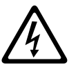
This symbol indicates that dangerous voltage constituting a risk of electric shock is present within this unit
This symbol indicates that there are important operating and maintenance instructions in the literature accompanying this unit
Safety Notice
- Prior to use, read through this safety guide.
- Pay attention to safety warnings.
- Observe all operating requirements.
- For any items designed for indoor use only, do not operate near water or in humid environments.
- For cleaning, only use a lint-free, dry cloth.
- Install according to the specifications.
- Place away from heat sources or heating appliances.
- During placement, ensure adequate support for the product and access to controls and connectors.
- Do not obstruct any cooling vents or openings and allow adequate space for air flow.
- Use only power connections supplied with the product or suitable equivalents.
- Do not modify the equipment in any way.
- For any mains powered appliances, ensure that the mains voltage is as described in the specifications.
- Keep powered products and batteries away from the reach of children.
- In case of malfunction, water ingress or other damage, consult qualified service personnel.
- Avoid pressure or impact to the housing that may result in damage when transporting or installing this product.
- For any Earthed mains product, ensure that the power supply has a protective Earth connection.
- Keep all packaging materials out of reach of children.
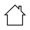
Indoor use only : The "House" symbol identifes electrical equipment designed primarily for indoor use.
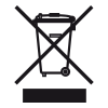
Disposal : The "Crossed Wheelie Bin" symbol on the product means that the product is classed as Electrical or Electronic equipment and should not be disposed with other household or commercial waste at the end of its useful life. The goods must be disposed of according to your local council guidelines.

AVSL Group Ltd, Unit 2 Bridgewater Park, Taylor Road, Manchester, M41 7JQ, Unitied Kingdom
AVSL (EUROPE) Ltd, Unit 3D North Point House, North Point Business Park, New Mallow Road, Cork, Ireland


