RP12
12 Channel DMX Relay Pack
154.113UK
Introduction
The 12CH DMX RELAY PACK can be controlled by DMX 512 console. Each output socket is controlled individually by one relay. It can be widely applied to entertainment hall, stage, social club and indoor building decoration.
 |
Caution: Please read this manual carefully before operating | |
|---|---|---|
| Damage caused by misuse is not covered by the warranty |
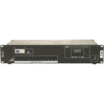
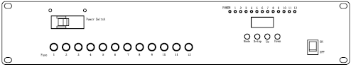
Front View
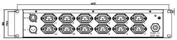
Rear View
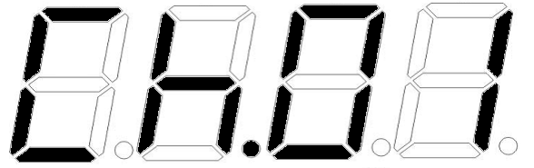
- LED digital display for DMX addressing and work mode setting
- universal DMX512 (1990) multiplexed digital control
- DMX and Stand Alone operation modes
There are two modes of operation:
DMX: Either: 1, 2, 3, 6 or 12 channel.
Manual control mode.
Each mode can be selected by first pressing the MODE button followed by the UP / DOWN buttons and SET to confirm. Each of the modes is displayed below:
Control Panel Menu
| MODE manual | SET UP manual | UP/DOWN manual | instruction |
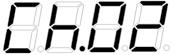
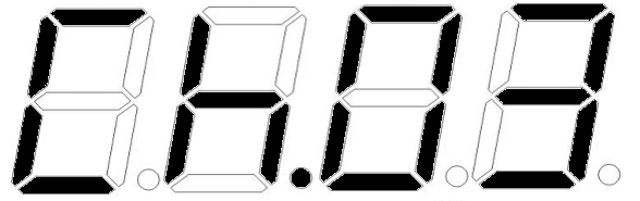
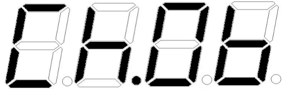
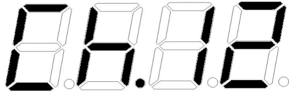
| DMX MODE | Address | A.001 ~ A.512 | Sets the DMX starting address |
| DMX Channels set | Ch.01 | The unit occupies 1 channels | |
| Ch.02 | The unit occupies 2 channels | ||
| Ch.03 | The unit occupies 3 channels | ||
| Ch.06 | The unit occupies 6 channels | ||
| Ch.12 | The unit occupies 12 channels | ||
MANUAL CONTROL MODE |
Manual Channels set | NA.01 | 12 output sockets occupy 1 channel |
| Na.02 | 12 output sockets occupy 2 channels | ||
| NA.03 | 12 output sockets occupy 3 channels | ||
| Na.06 | 12 output sockets occupy 6 channels | ||
| NA.12 | 12 output sockets occupy 12 channels | ||
Manual Channels Open/ close |
01.on / 01.oF | 01.on: set channel 1 open 01.oF: set channel 1 close | |
| 02.on / 02.oF | 02.on :set channel 2 open 02.oF :set channel 2 close | ||
| 03.on / 03.oF | 03.on :set channel 3 open 03.oF :set channel 3 close | ||
| 04.on / 04.oF | 04.on :set channel 4 open 04.oF :set channel 4 close | ||
| 05.on / 05.oF | 05.on :set channel 5 open 05.oF :set channel 5 close | ||
| 06.on / 06.oF | 06.on :set channel 6 open 06.oF :set channel 6 close | ||
| 07.on / 07.oF | 07.on :set channel 7 open 07.oF :set channel 7 close | ||
| 08.on / 08.oF | 08.on :set channel 8 open 08.oF :set channel 8 close | ||
| 09.on / 09.oF | 09.on :set channel 9 open 09.oF :set channel 9 close | ||
| 10.on / 10.oF | 10.on :set channel 10 open 10.oF :set channel 10 close | ||
| 11.on / 11.oF | 11.on :set channel 11 open 11.oF :set channel 11 close | ||
| 12.on / 12.oF | 12.on :set channel 12 open 12.oF :set channel 12 close | ||
OTHER MODE |
Display on/off |
don | LED digital tube display always on |
| doFF | LED digital tube display off | ||
Display normal/ inversed |
Stnd | LED digital tube display normal | |
| n3r | LED digital tube display inversed | ||
Initialization mode |
dEFA | Initialize the unit at the extra factory setting |
DMX Mode
You can control devices individually via the sliders on your DMX-controller. Each of the values is listed below
1 channel mode
| CH No. | DMX value | Function |
| CH1 | 000~010 | CLOSE(No.1- 12 OUTPUT SOCKET) |
| 011~255 | OPEN(No.1-12 OUTPUT SOCKET) |
2 channels mode
| CH No. | DMX value | Function |
| CH1 | 000~010 | CLOSE(No.1-6 OUTPUT SOCKET) |
| 011~255 | OPEN(No.1-6 OUTPUT SOCKET) | |
| CH2 | 000~010 | CLOSE(No.7-12 OUTPUT SOCKET) |
| 011~255 | OPEN(No.7-12 OUTPUT SOCKET) |
3 channels mode
| CH No. | DMX value | Function |
| CH1 | 000~010 | CLOSE(No.1-4 OUTPUT SOCKET) |
| 011~255 | OPEN(No.1-4 OUTPUT SOCKET) | |
| CH2 | 000~010 | CLOSE(No.5-8 OUTPUT SOCKET) |
| 011~255 | OPEN(No.5-8 OUTPUT SOCKET) | |
| CH3 | 000~010 | CLOSE(No.9-12 OUTPUT SOCKET) |
| 011~255 | OPEN(No.9-12 OUTPUT SOCKET) |
6 channels mode
| CH No. | DMX value | Function |
| CH1 | 000~010 | CLOSE(No.1-2 OUTPUT SOCKET) |
| 011~255 | OPEN(No.1-2 OUTPUT SOCKET) | |
| CH2 | 000~010 | CLOSE(No.3-4 OUTPUT SOCKET) |
| 011~255 | OPEN(No.3-4 OUTPUT SOCKET) | |
| CH3 | 000~010 | CLOSE(No.5-6 OUTPUT SOCKET) |
| 011~255 | OPEN(No.5-6 OUTPUT SOCKET) | |
| CH4 | 000~010 | CLOSE(No.7-8 OUTPUT SOCKET) |
| 011~255 | OPEN(No.7-8 OUTPUT SOCKET) | |
| CH5 | 000~010 | CLOSE(No.9-10 OUTPUT SOCKET) |
| 011~255 | OPEN(No.9-10 OUTPUT SOCKET) | |
| CH6 | 000~010 | CLOSE(No.11-12 OUTPUT SOCKET) |
| 011~255 | OPEN(No.11-12 OUTPUT SOCKET) |
12 channels mode
| CH No. | DMX value | Function |
| CH1 | 000~010 | CLOSE(No.1 OUTPUT SOCKET) |
| 011~255 | OPEN(No.1 OUTPUT SOCKET) | |
| CH2 | 000~010 | CLOSE(No.2 OUTPUT SOCKET) |
| 011~255 | OPEN(No.2 OUTPUT SOCKET) | |
| CH3 | 000~010 | CLOSE(No.3 OUTPUT SOCKET) |
| 011~255 | OPEN(No.3 OUTPUT SOCKET) | |
| CH4 | 000~010 | CLOSE(No.4 OUTPUT SOCKET) |
| 011~255 | OPEN(No.4 OUTPUT SOCKET) | |
| CH5 | 000~010 | CLOSE(No.5 OUTPUT SOCKET) |
| 011~255 | OPEN(No.5 OUTPUT SOCKET) | |
| CH6 | 000~010 | CLOSE(No.6 OUTPUT SOCKET) |
| 011~255 | OPEN(No.6 OUTPUT SOCKET) | |
| CH7 | 000~010 | CLOSE(No.7 OUTPUT SOCKET) |
| 011~255 | OPEN(No.7 OUTPUT SOCKET) | |
| CH8 | 000~010 | CLOSE(No.8 OUTPUT SOCKET) |
| 011~255 | OPEN(No.8 OUTPUT SOCKET) | |
| CH9 | 000~010 | CLOSE(No.9 OUTPUT SOCKET) |
| 011~255 | OPEN(No.9 OUTPUT SOCKET) | |
| CH10 | 000~010 | CLOSE(No.10 OUTPUT SOCKET) |
| 011~255 | OPEN(No.10 OUTPUT SOCKET) | |
| CH11 | 000~010 | CLOSE(No.11 OUTPUT SOCKET) |
| 011~255 | OPEN(No.11 OUTPUT SOCKET) | |
| CH12 | 000~010 | CLOSE(No.12 OUTPUT SOCKET) |
| 011~255 | OPEN(No.12 OUTPUT SOCKET) |
Specification
| Specification | Value |
|---|---|
| Power supply | 230Vac, 50Hz |
| Maximum current input | 30A |
| Maximum current per channel | 10A |
| IEC outputs | 12 |
| Dimensions | 440 x 205 x 88mm |
| Weight | 3.8kg |
Precautions
| CAUTION | ||
| RISK OF ELECTRIC SHOCK DO NOT OPEN | ||
| CAUTION : TO REDUCE THE RISK OF ELECTRIC SHOCK, DO NOT REMOVE COVER (OR BACK) NO USER-SERVICEABLE PARTS INSIDE REFER SERVICING TO QUALIFIED SERVICE PERSONNEL | ||
This symbol indicates that dangerous voltage constituting a risk of electric shock is present within this unit
This symbol indicates that there are important operating and maintenance instructions in the literature accompanying this unit
Safety Notice
- Prior to use, read through this safety guide.
- Pay attention to safety warnings.
- Observe all operating requirements.
- For any items designed for indoor use only, do not operate near water or in humid environments.
- For cleaning, only use a lint-free, dry cloth.
- Install according to the specifications.
- Place away from heat sources or heating appliances.
- During placement, ensure adequate support for the product and access to controls and connectors.
- Do not obstruct any cooling vents or openings and allow adequate space for air flow.
- Use only power connections supplied with the product or suitable equivalents.
- Do not modify the equipment in any way.
- For any mains powered appliances, ensure that the mains voltage is as described in the specifications.
- Keep powered products and batteries away from the reach of children.
- In case of malfunction, water ingress or other damage, consult qualified service personnel.
- Avoid pressure or impact to the housing that may result in damage when transporting or installing this product.
- For any Earthed mains product, ensure that the power supply has a protective Earth connection.
- Keep all packaging materials out of reach of children.
Indoor use only : The "House" symbol identifes electrical equipment designed primarily for indoor use.
Disposal : The "Crossed Wheelie Bin" symbol on the product means that the product is classed as Electrical or Electronic equipment and should not be disposed with other household or commercial waste at the end of its useful life. The goods must be disposed of according to your local council guidelines.
AVSL Group Ltd, Unit 2 Bridgewater Park, Taylor Road, Manchester, M41 7JQ, Unitied Kingdom
AVSL (EUROPE) Ltd, Unit 3D North Point House, North Point Business Park, New Mallow Road, Cork, Ireland