TETRA
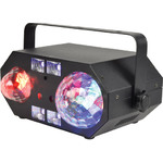
Tetra: LED Moonflower + Ripple + Strobe/UV + Laser Effect
151.608UK
Introduction
Thank you for your purchase of the QTX TETRA light effect. This model can deliver an extra wide array of colourful projections coupled with powerful UV/strobe and laser effects. Please read and keep this user manual to get the best from your purchase and avoid damage through misuse.
Safety
Check for correct mains voltage and condition of power lead before connecting to a power outlet.
Placement
- Use the included mounting bracket to fix to a stand or lighting truss.
- Use secondary safety fixings if mounting overhead.
- Ensure adequate airflow around the fixture housings.
- Ensure adequate access to controls and connections.
- Do not aim LED or laser output directly into line of sight, as this can result in eye injury.
Cleaning
- Use a soft cloth with a neutral detergent to clean the casing as required.
- Do not use strong solvents for cleaning the unit.
In The Box
Please open the package carefully and check that all contents are present and in good condition.
Contact your retailer if any part is missing or broken.
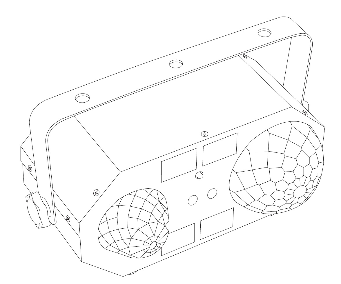
- TETRA LED & laser light effect
- I.R. remote control
- Mounting bracket
- UK mains plug to IEC lead
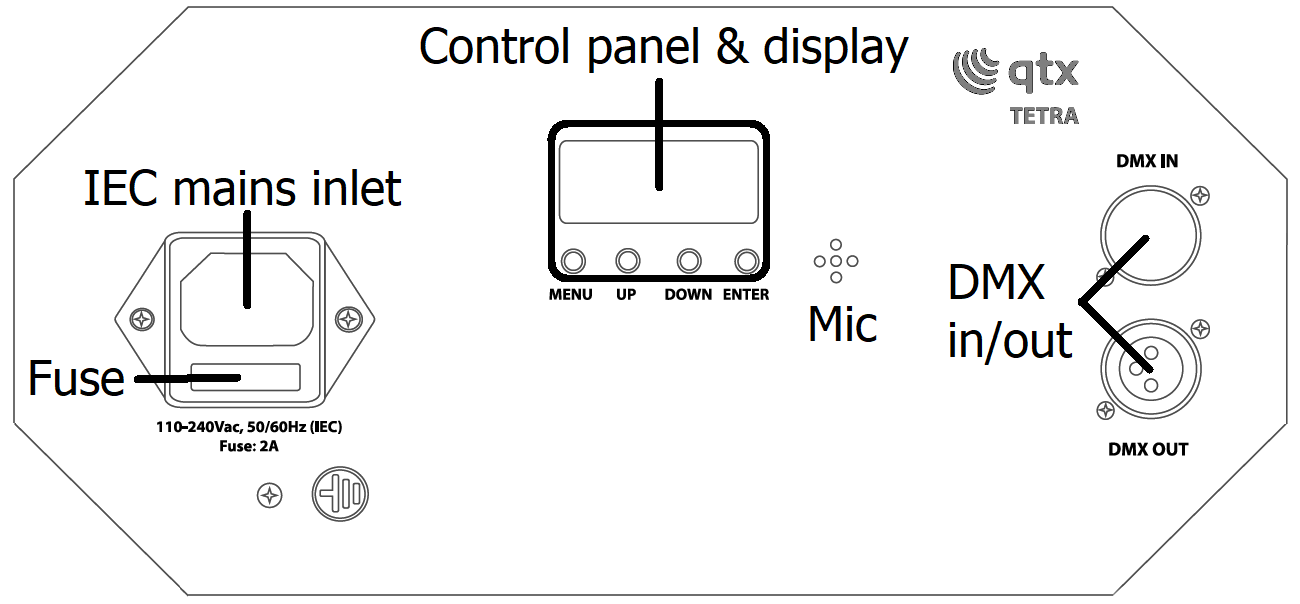
Rear Panel
Installation
Install the TETRA free standing on a stable surface or suspended from a lighting stand or truss.
When mounting to a stand or truss, use the included adjustable fixing bracket and ensure that a safety wire is used if mounting overhead.
If the TETRA is to be operated by DMX control, connect the DMX control signal to the DMX IN connector using an XLR lead and connect further DMX fixtures being controlled from the DMX OUT connector.
Connect mains power to the TETRA using the supplied IEC lead or equivalent, ensuing the supply voltage is correct and capable of the load demand.
Remote Control
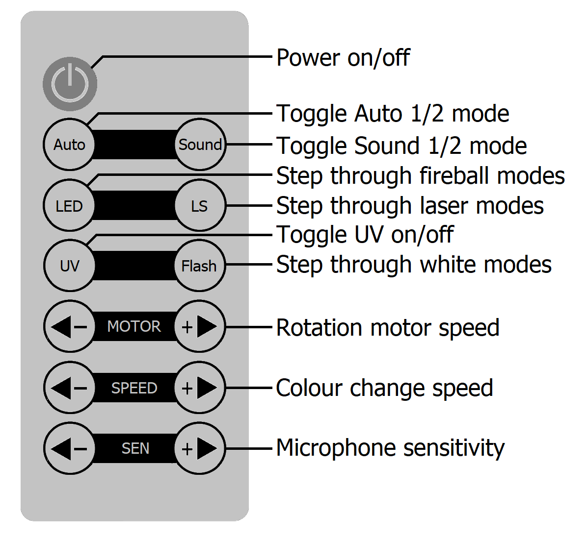
The TETRA is supplied with an infra-red remote control for quick operation.
This is powered by a CR2025 button cell, which should be engaged by pulling out the plastic tab.
Point the remote towards the front of the TETRA housing, where the I.R. receiver is located.
The remote controls are explained in the diagram below
Onboard Menu
For more detailed setup and operation, the TETRA has an onboard control panel at the rear.
Using the MENU, UP, DOWN, ENTER buttons to navigate gives in-depth control of the internal functions.
The onboard control menu functions are described in the table below.
| Mode | Display | Function | Press Enter | Press Enter |
|---|---|---|---|---|
| Axxx | A001 - AS12 | DMX start address | ||
| PUxx | PUOn | UV On | ||
| PUOF | UV Off | |||
| LAxx | LAoF | Laser off | ||
| LAAu | Laser Auto program | SP 1 - SP 9rotation speed | ||
| LA r | Red only | |||
| LA 9 | Green only | |||
| LAr9 | Red + Green combined | |||
| LAO1 - LA20 | Red/Green Auto programs | |||
| LExx | LE 1 | Red fireball | SP 1 - SP 9rotation speed | |
| LE 2 | Green fireball | |||
| LE 3 | Blue fireball | |||
| LE 4 | Colour change fireball | Sd 1 - Sd 9 colour speed | SP 1 - SP 9 rotation speed | |
| LE 5 | Strobe fireball | Sd 1 - Sd 9 strobe speed | SP 1 - SP 9 rotation speed | |
| LE 6 | Auto fireball | Sd 1 - Sd 9 colour speed | SP 1 - SP 9 rotation speed | |
| FLxx | FLoF | White flood off | ||
| FL 1 | White flood on | |||
| FL 2 - 9 | White strobe fast to slow | |||
| PA x | PA 1 | Red water effect | SP 1 - SP 9 rotation speed | |
| PA 2 | Green water effect | |||
| PA 3 | Blue water effect | |||
| PA 4 | White water effect | |||
| PA 5 | Colour water fx 4 step | Sd 1 - Sd 9 colour speed | SP 1 - SP 9 rotation speed | |
| PA 6 | Colour water fx 30 step | Sd 1 - Sd 9 colour speed | SP 1 - SP 9 rotation speed | |
| PA 7 | Strobe water effect | Sd 1 - Sd 9 strobe speed | SP 1 - SP 9 rotation speed | |
| PA 8 | Colour water 4 & 30 step | Sd 1 - Sd 9 colour speed | SP 1 - SP 9 rotation speed | |
| AUxx | AU 1 | Auto Mode 1 | ||
| AU 2 | Auto Mode 2 | |||
| S1xx | S101 - S120 | Sound Mode 1 (last 2 digits are beat step 1-20) | ||
| uoL1 - uoL9 | Mic sensitivity | |||
| S2xx | S201 - S220 | Sound Mode 2 (last 2 digits are beat step 1-20) | ||
| uoL1 - uoL9 | Mic sensitivity |
Standalone Operation
As described in the menu above, the TETRA can be operated in standalone mode by setting the operation of water effect, fireball, UV and white flood/strobe LEDs. Various preset, auto and sound-activated modes can also be accessed using the I.R. remote control.
DMX Operation
The TETRA light effect is compatible with standard DMX512 control.
Connect a DMX controller to the TETRA using an XLR DMX lead into the DMX IN connector.
Connect further DMX light fixtures that are being controlled from the DMX OUT connector to the DMX IN of each fixture in a daisy-chain.
Set the DMX start address of the TETRA and all other lighting fixtures in the chain to accommodate all the required channels for each. The TETRA has 11 DMX channels and the table below is described with the DMX start address set to
DMX Channels
| Channel | Value | Function |
|---|---|---|
| 1 | 000 - 024 | Water wave LED off |
| 025 - 255 | Water wave step through colours | |
| 2 | 000 - 009 | White LED off |
| 010 - 255 | White LED on | |
| 3 | 000 - 009 | Fireball off |
| 010 - 044 | Fireball Red | |
| 045 - 079 | Fireball Green | |
| 080 - 114 | Fireball Blue | |
| 115 - 149 | Fireball Red + Green | |
| 150 - 184 | Fireball Green + Blue | |
| 185 - 219 | Fireball Red + Blue | |
| 220 - 255 | Fireball Red + Green + Blue | |
| 4 | 000 - 009 | Laser off |
| 010 - 099 | Laser Red | |
| 100 - 199 | Laser Green | |
| 200 - 255 | Laser Red + Green | |
| 5 | 000 - 009 | UV off |
| 010 - 255 | UV on | |
| 6 | 000 - 007 | All effects on |
| 008 - 255 | Combinations of 1, 2, 3 or 4 effects | |
| 7 | 000 - 009 | Strobe off |
| 010 - 255 | Strobe fast to slow | |
| 8 | 000 - 009 | Water wave motor off |
| 010 - 255 | Water wave motor fast to slow | |
| 9 | 000 - 009 | Fireball motor off |
| 010 - 255 | Fireball motor fast to slow | |
| 10 | 000 - 009 | Laser motor off |
| 010 - 127 | Laser motor fast to slow clockwise | |
| 128 - 255 | Laser motor slow to fast anticlockwise | |
| 11 | 000 - 050 | Manual setting from DMX channels 1-10 |
| 051 - 150 | Auto program 1 | |
| 151 - 200 | Auto program 2 | |
| 201 - 250 | Sound program 1 | |
| 251 - 255 | Sound program 2 |
Specification
| Specification | Value |
|---|---|
| Power supply | 110-240Vac, 50/60Hz (IEC) |
| Power consumption | 30W |
| Fuse rating | 2A |
| LED : power | 6 x 3W moonflower, 4W RGBW ripple, 4 x 2W UV/Strobe |
| Laser power | 30mW + 100mW (green + red) |
| Laser colour | Green (523nm), Red (650nm) |
| Laser class | 3B |
| DMX connection | XLRM in, XLRF out |
| DMX channels | 11 |
| Battery : remote | CR2025 (supplied) |
| Dimensions | 270 x 160 x 110mm |
| Weight | 1.45kg |
Precautions
| CAUTION | ||
| RISK OF ELECTRIC SHOCK DO NOT OPEN | ||
| CAUTION : TO REDUCE THE RISK OF ELECTRIC SHOCK, DO NOT REMOVE COVER (OR BACK) NO USER-SERVICEABLE PARTS INSIDE REFER SERVICING TO QUALIFIED SERVICE PERSONNEL | ||
This symbol indicates that dangerous voltage constituting a risk of electric shock is present within this unit
This symbol indicates that there are important operating and maintenance instructions in the literature accompanying this unit
Safety Notice
- Prior to use, read through this safety guide.
- Pay attention to safety warnings.
- Observe all operating requirements.
- For any items designed for indoor use only, do not operate near water or in humid environments.
- For cleaning, only use a lint-free, dry cloth.
- Install according to the specifications.
- Place away from heat sources or heating appliances.
- During placement, ensure adequate support for the product and access to controls and connectors.
- Do not obstruct any cooling vents or openings and allow adequate space for air flow.
- Use only power connections supplied with the product or suitable equivalents.
- Do not modify the equipment in any way.
- For any mains powered appliances, ensure that the mains voltage is as described in the specifications.
- Keep powered products and batteries away from the reach of children.
- In case of malfunction, water ingress or other damage, consult qualified service personnel.
- Avoid pressure or impact to the housing that may result in damage when transporting or installing this product.
- For any Earthed mains product, ensure that the power supply has a protective Earth connection.
- Keep all packaging materials out of reach of children.
Indoor use only : The "House" symbol identifes electrical equipment designed primarily for indoor use.
Disposal : The "Crossed Wheelie Bin" symbol on the product means that the product is classed as Electrical or Electronic equipment and should not be disposed with other household or commercial waste at the end of its useful life. The goods must be disposed of according to your local council guidelines.
AVSL Group Ltd, Unit 2 Bridgewater Park, Taylor Road, Manchester, M41 7JQ, Unitied Kingdom
AVSL (EUROPE) Ltd, Unit 3D North Point House, North Point Business Park, New Mallow Road, Cork, Ireland