Stereo Bar
Stereo Twin PAR Bar
151.554UK
Introduction

Safety Instructions
- Please keep this manual for future reference.
- Always make sure that you are connecting to the proper voltage, and that the line voltage you are connecting to is not higher than that stated on the bottom of the fixture.
- This product is intended for indoor use only. It must be connected to an earthed mains outlet.
- To prevent risk of fire or shock, do not expose fixture to rain or moisture. Make sure there are no flammable materials close to the unit while operating.
- The unit must be installed in a location with adequate ventilation, at least 20cm from adjacent surfaces. Be sure that no ventilation slots are obstructed.
- Always disconnect from power source before servicing or replacing fuse and be sure to replace with same fuse size and type.
- Maximum ambient temperature is 40°C. Do not operate the fixture at higher temperatures.
- In the event of a serious operating problem, stop using the unit immediately. Never try to repair the unit by yourself. Repairs carried out by unskilled people can lead to damage or malfunction. Please contact the nearest authorised technical assistance centre.
- Make sure the power cord is never crimped or damaged.
- Never disconnect the power cord by pulling or tugging on the cord.
- Avoid direct eye exposure to the light source while it is on.
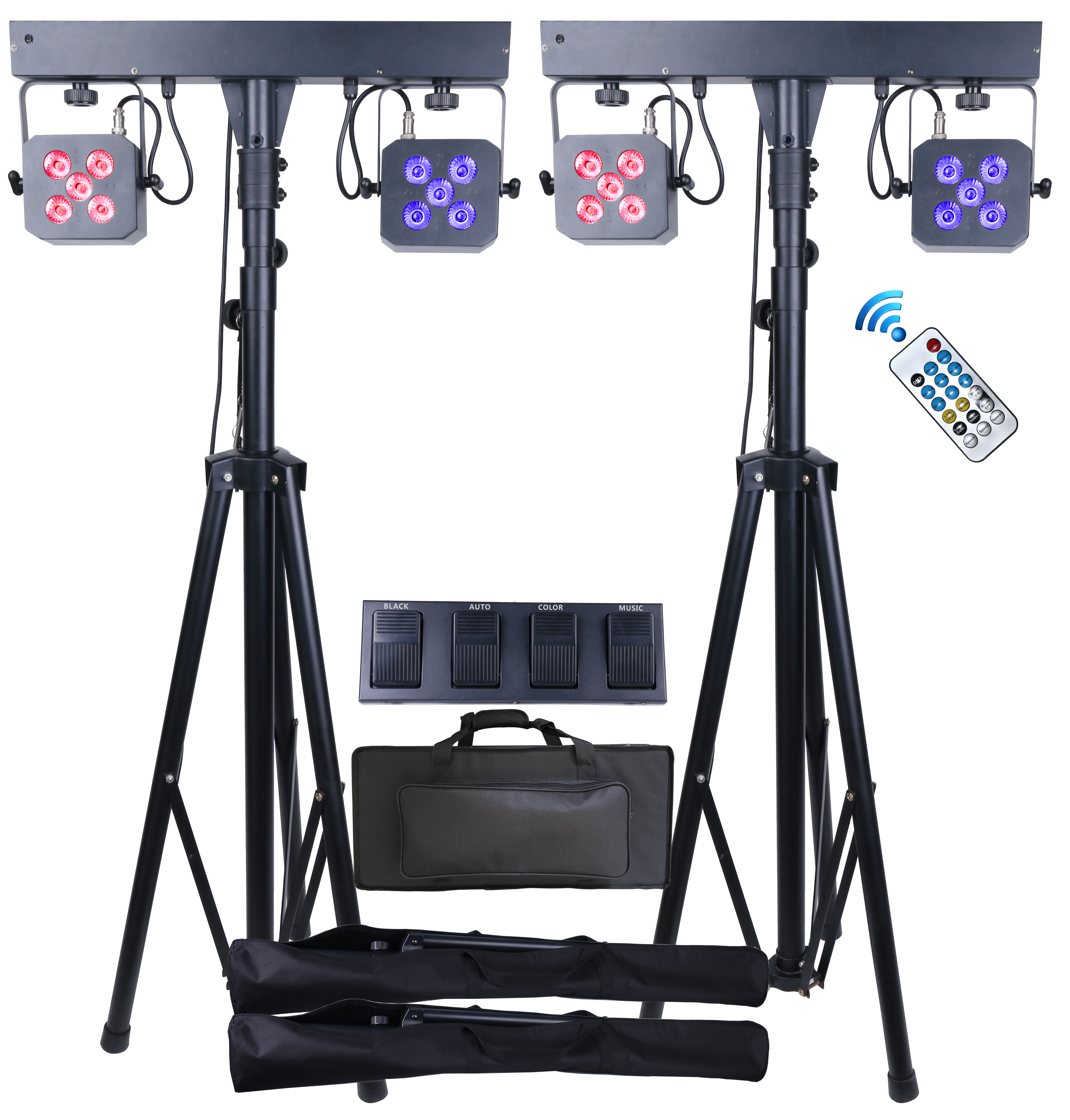
Contents In The Box**
- PAR Bar x2
- Tripod stand x2
- Foot Controller
- Remote control
- Carry Case for Par Bar and Foot control
- Carry case for tripod x2
- Instruction Manual
- Power cable x2
- 10M DMX cable
- Hanging Bracket and Screw Set x4
Features
- Twin PAR Bar lighting set with 2x2x5pcs 10W Quad LEDs
- High output with 3255Lux at 2M when full on with one separate head
- Saturated wash effect without multicoloured shadows
- Foot controller with 10M cable and IR remote control
- Separate light head control with various built-in colour macros
- Easy setup and tear-down with tripod stand and carrying bags
Setup/Installation
This lightweight, versatile PAR bar system is prefect for mobile DJs and performers who need their lighting to be quick to set up and easily transportable. 4 PAR Cans are each loaded with 5 LEDs in red, green, blue and white for super smooth colour blending.
- Remove stands from the carrier and open the tripod legs onto the floor, make sure it is on a stable footing.
- Remove the PAR bars from the main carrier and attach them onto the tripod stand.
- Tighten the screw to secure the PAR bar.
- Connect the Power cables on both units.
- Setting the PAR BARs to Master and Slave (see PAR Bar mode settings.)
- Connect the multi-core lead to the foot controller and the Master unit.
- Connect the XLR cable (3 Pins) to the DMX OUT socket on the Master unit and the DMX IN socket on the Slave unit.
- Adjust height of the extension pole, insert safety pin and tighten the locking screw.
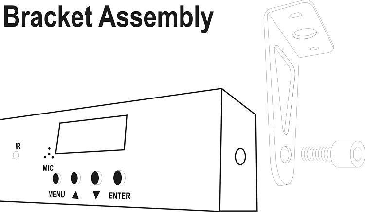
Hanging Brackets are included for permanent fitting on trusses (Truss attachments are not included) or screw to the ceilings. Attach bracket with screw onto the ends of the PAR bar as shown: -
PAR Bar Mode Setting
When using the unit for the first time or resetting to default, it is recommended a factory default reset is performed.
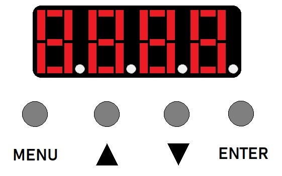
Factory Default Setting
Press the MENU button once, display will show
 .
.Press UP button once, display will show
 .
.Press the Enter button once, display will show
 This means that you have set unit to Default setting, the unit now is in Slave mode.
Function Menu Table
Below is a table showing the options and settings available for the PAR Bar, Press the MENU button once and you can scroll the function list in the order as shown. Press the Enter button once to access the range setting, then pressing Up/Down buttons allows you to adjust the setting, press enter to select or Menu to exit.
| Function | Display | Range | Feature |
|---|---|---|---|
| Address | aDDR | A001-A512 | DMX512 addressing |
| Channel | Chnd | 06ch 09ch 10ch 13ch |
6 DMX Channels 9 DMX Channels 10 DMX Channels 13 DMX Channels |
| Show Mode | Shnd | Sh01-sh04 | Modes 1-4 |
| Slave/Master | Slnd | SL 1 MAst |
Slave Mode Master Mode |
| Non DMX | LOst | auto soun blac hold |
Auto Sound Black Out Hold |
| Speed | Sped | SP01-SP99 | Speed Adjust |
| Sensitivity | Sens | S001-S099 | Sound Sensitivity |
| Mirroring | NIOR | On/Off | Mirroring Mode |
| Display | DISP | On/Off | Display Reverse |
| Time | FhRS | 001H | Shows Working Time |
| Version | VER | V1.1 | Shows Software Version |
| Factory Default | DEFA | A001 | Enter Factory Default Setting |
Foot Controller
To use the Foot Controller, it must be connected to the PAR Bar set as the Master and switch on the power at the back of the Foot Controller. When a DMX controller is connected to the PAR Bar it overrides the foot controller.
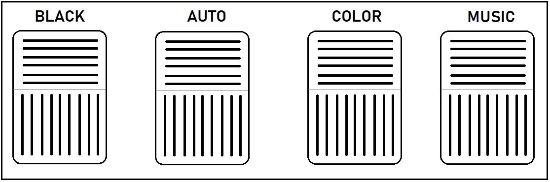
| Pedal | Function |
|---|---|
| BLACK | Press once - Black Out Mode Press and Hold – (On Auto Mode only) Strobe feature is activated while it is held down. |
| AUTO | Auto Mode – perform preprogrammed schemes |
| COLOR | Colour Mode - |
| MUSIC | Sound Mode – The rhythm of the light will be synced to the sound picked up by the mic. |
Remote Control
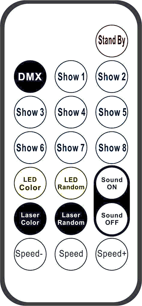
| Button | Functions |
|---|---|
| Stand By | Power On/Off |
| DMX | DMX mode |
| Show 1 | Show 1 |
| Show 2 | Show 2 |
| Show 3 | Show 3 |
| Show 4 | Show 4 |
| Show 5 | Show 5 |
| Show 6 | No function |
| Show 7 | No function |
| Show 8 | No function |
| Led Color | LED color Jump |
| LED Random | No function |
| Sound on | Sound on |
| Laser color | No function |
| Laser Random | No function |
| Sound Off | Sound off |
| Speed- | Show1-show4 speed increase |
| Speed | Show1-show8 speed in middle(default) |
| Speed+ | Show1-show8 speed decrease |
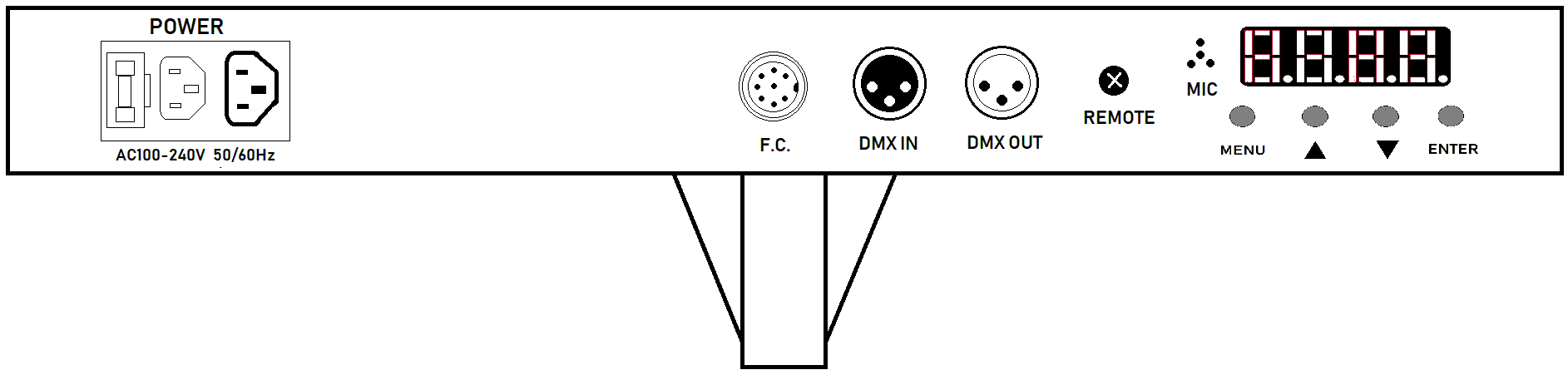
DMX Connection and Control
The PAR Bar can be connected as a daisy chain by using standard XLR cables. The units are labelled with DMX IN and DMX OUT –
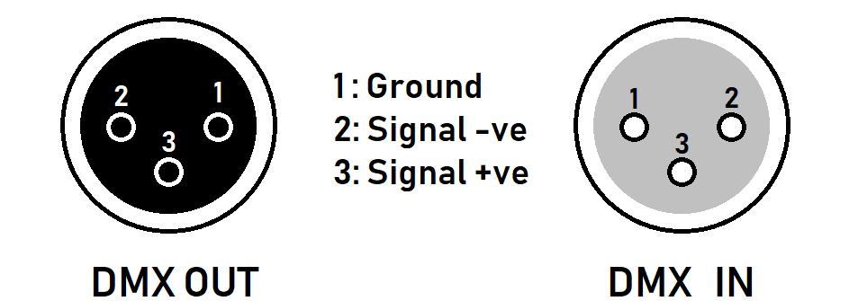
Connect the DMX controller output to the DMX IN on the first unit. Then connect the first unit’s DMX OUT to DMX IN on the next unit, and so on if there are more units. A DMX starting address must be assigned to each fixture; allowing the DMX controller to control each fixture individually. This fixture has 13 channels so the first unit should be assigned with an address of 001, the next unit should be 014 (13+1) and next one at 027 (2x13+1) etc. All fixtures can be set to the same address, this way all connected the fixtures will be act in unison. Please refer to the DMX tables for the function and features.
DMX Terminator
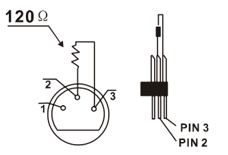
If there are many lines or lights, it is recommended to use a DMX terminator to prevent DMX signal corruption, the DMX terminator is an simple XLR plug with a 120 Ω resistor connected between pins 2 and 3,which is then plugged into the output XLR socket of the last fixture in the chain.
DMX Control Table
6CH Mode
| Channel | Function | Value | Description |
|---|---|---|---|
| 1CH | Master dimmer | 0-255 | Master dimmer |
| 2CH | Strobe | 000-015 | OFF |
| 016-030 | ON | ||
| 031-090 | Variable strobe from slow to fast | ||
| 091-105 | on | ||
| 106-165 | Pulse effect from slow to fast | ||
| 166-180 | on | ||
| 181-240 | Random strobe from slow to fast | ||
| 241-255 | on | ||
| 3CH | Red dimmer | 0-255 | Red dimming |
| 4CH | Green dimmer | 0-255 | Green dimming |
| 5CH | Blue dimmer | 0-255 | Blue dimming |
| 6CH | White dimmer | 0-255 | White dimming |
9CH Mode
| Channel | Function | Value | Description |
|---|---|---|---|
| 1CH | Master dimmer | 0-255 | Master dimmer |
| 2CH | Strobe | 000-015 | OFF |
| 016-030 | ON | ||
| 031-090 | Variable strobe from slow to fast | ||
| 091-105 | on | ||
| 106-165 | Pulse effect from slow to fast | ||
| 166-180 | on | ||
| 181-240 | Random strobe from slow to fast | ||
| 241-255 | on | ||
| 3CH | Red dimmer | 0-255 | Red dimming |
| 4CH | Green dimmer | 0-255 | Green dimming |
| 5CH | Blue dimmer | 0-255 | Blue dimming |
| 6CH | White dimmer | 0-255 | White dimming |
| 7CH | Color macro | 0-15 | No function |
| 16-175 | Color mixing | ||
| 176-255 | Color fading from slow to fast | ||
| 8CH | Show mode | 0-15 | No function |
| 16-63 | Show 1 | ||
| 64-111 | Show 2 | ||
| 112-159 | Show 3 | ||
| 160-207 | Show 4 | ||
| 208-255 | Show 5 | ||
| 9CH | Speed | 0-250 | Sound off, Auto Speed from slow to fast |
| 251-255 | Sound On |
10CH Mode
| Channel | Function | Value | Description |
|---|---|---|---|
| 1CH | Master dimmer | 0-255 | Master dimmer |
| 2CH | Strobe | 000-015 | OFF |
| 016-030 | ON | ||
| 031-090 | Variable strobe from slow to fast | ||
| 091-105 | on | ||
| 106-165 | Pulse effect from slow to fast | ||
| 166-180 | on | ||
| 181-240 | Random strobe from slow to fast | ||
| 241-255 | on | ||
| 3CH | Red 1 dimmer | 0-255 | Red1 dimming |
| 4CH | Green1 dimmer | 0-255 | Green1 dimming |
| 5CH | Blue1 dimmer | 0-255 | Blue1 dimming |
| 6CH | White1 dimmer | 0-255 | White1 dimming |
| 7CH | Red 2 dimmer | 0-255 | Red2 dimming |
| 8CH | Green2 dimmer | 0-255 | Green2 dimming |
| 9CH | Blue2 dimmer | 0-255 | Blue2 dimming |
| 10CH | White2 dimmer | 0-255 | White2 dimming |
13CH Mode
| Channel | Function | Value | Description |
|---|---|---|---|
| 1CH | Master dimmer | 0-255 | Master dimmer |
| 2CH | Strobe | 000-015 | OFF |
| 016-030 | ON | ||
| 031-090 | Variable strobe from slow to fast | ||
| 091-105 | on | ||
| 106-165 | Pulse effect from slow to fast | ||
| 166-180 | on | ||
| 181-240 | Random strobe from slow to fast | ||
| 241-255 | on | ||
| 3CH | Red1 dimmer | 0-255 | Red1 dimming |
| 4CH | Green1 dimmer | 0-255 | Green1 dimming |
| 5CH | Blue1 dimmer | 0-255 | Blue1 dimming |
| 6CH | White1 dimmer | 0-255 | White1 dimming |
| 7CH | Red2 dimmer | 0-255 | Red2 dimming |
| 8CH | Green2 dimmer | 0-255 | Green2 dimming |
| 9CH | Blue2 dimmer | 0-255 | Blue2 dimming |
| 10CH | White2 dimmer | 0-255 | White2 dimming |
| 11CH | Color macro | 0-15 | No function |
| 16-175 | Color mixing | ||
| 176-255 | Color fading from slow to fast | ||
| 12CH | Show mode | 0-15 | No function |
| 16-63 | Show 1 | ||
| 64-111 | Show 2 | ||
| 112-159 | Show 3 | ||
| 160-207 | Show 4 | ||
| 208-255 | Show 5 | ||
| 13CH | Speed | 0-250 | Sound off, Auto Speed from slow to fast |
| 251-255 | Sound On |
Specification
| Specification | Value |
|---|---|
| Power supply | 220-240Vac, 50/60Hz (IEC) |
| Fuse rating | 2A |
| DMX channels | DMX 512 mode (6, 9, 10 or 13Channel) |
| Power consumption | 200W |
| LED : qty per can | 5 x 10W RGBW 4in1 LED |
| Strobe speed | 1-25 Hz |
| LED : lifespan | 50,000 hours |
| Beam angle | 25° |
| Lumens | 3255 lux @ 2m |
| IP rating | IP 20 |
| Height adjustment | 1140 – 1870mm |
| Dimensions | Par Bar: 600x245x65mm, Stand: 140x110x1025, Carry Bag: 660x300x220mm |
| Weight | 17Kg |
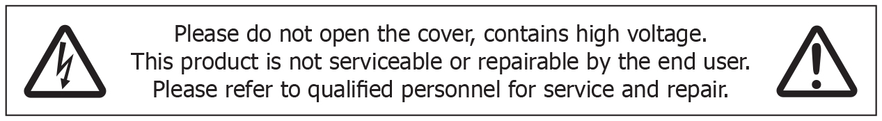
Precautions
| CAUTION | ||
| RISK OF ELECTRIC SHOCK DO NOT OPEN | ||
| CAUTION : TO REDUCE THE RISK OF ELECTRIC SHOCK, DO NOT REMOVE COVER (OR BACK) NO USER-SERVICEABLE PARTS INSIDE REFER SERVICING TO QUALIFIED SERVICE PERSONNEL | ||
This symbol indicates that dangerous voltage constituting a risk of electric shock is present within this unit
This symbol indicates that there are important operating and maintenance instructions in the literature accompanying this unit
Safety Notice
- Prior to use, read through this safety guide.
- Pay attention to safety warnings.
- Observe all operating requirements.
- For any items designed for indoor use only, do not operate near water or in humid environments.
- For cleaning, only use a lint-free, dry cloth.
- Install according to the specifications.
- Place away from heat sources or heating appliances.
- During placement, ensure adequate support for the product and access to controls and connectors.
- Do not obstruct any cooling vents or openings and allow adequate space for air flow.
- Use only power connections supplied with the product or suitable equivalents.
- Do not modify the equipment in any way.
- For any mains powered appliances, ensure that the mains voltage is as described in the specifications.
- Keep powered products and batteries away from the reach of children.
- In case of malfunction, water ingress or other damage, consult qualified service personnel.
- Avoid pressure or impact to the housing that may result in damage when transporting or installing this product.
- For any Earthed mains product, ensure that the power supply has a protective Earth connection.
- Keep all packaging materials out of reach of children.
Indoor use only : The "House" symbol identifes electrical equipment designed primarily for indoor use.
Disposal : The "Crossed Wheelie Bin" symbol on the product means that the product is classed as Electrical or Electronic equipment and should not be disposed with other household or commercial waste at the end of its useful life. The goods must be disposed of according to your local council guidelines.
AVSL Group Ltd, Unit 2 Bridgewater Park, Taylor Road, Manchester, M41 7JQ, Unitied Kingdom
AVSL (EUROPE) Ltd, Unit 3D North Point House, North Point Business Park, New Mallow Road, Cork, Ireland
